L1 L2 L3
7
8
9
10
11
12
1
2
3
4
5
6
1/5A
N
1/5A
N
1/5A
N
IL1B
IL2B
IL3B
X120
X120
1/5A
N
1/5A
N
1/5A
N
IL1
IL2
IL3
P1
P2
P1
P2
S1
S2
S1
S2
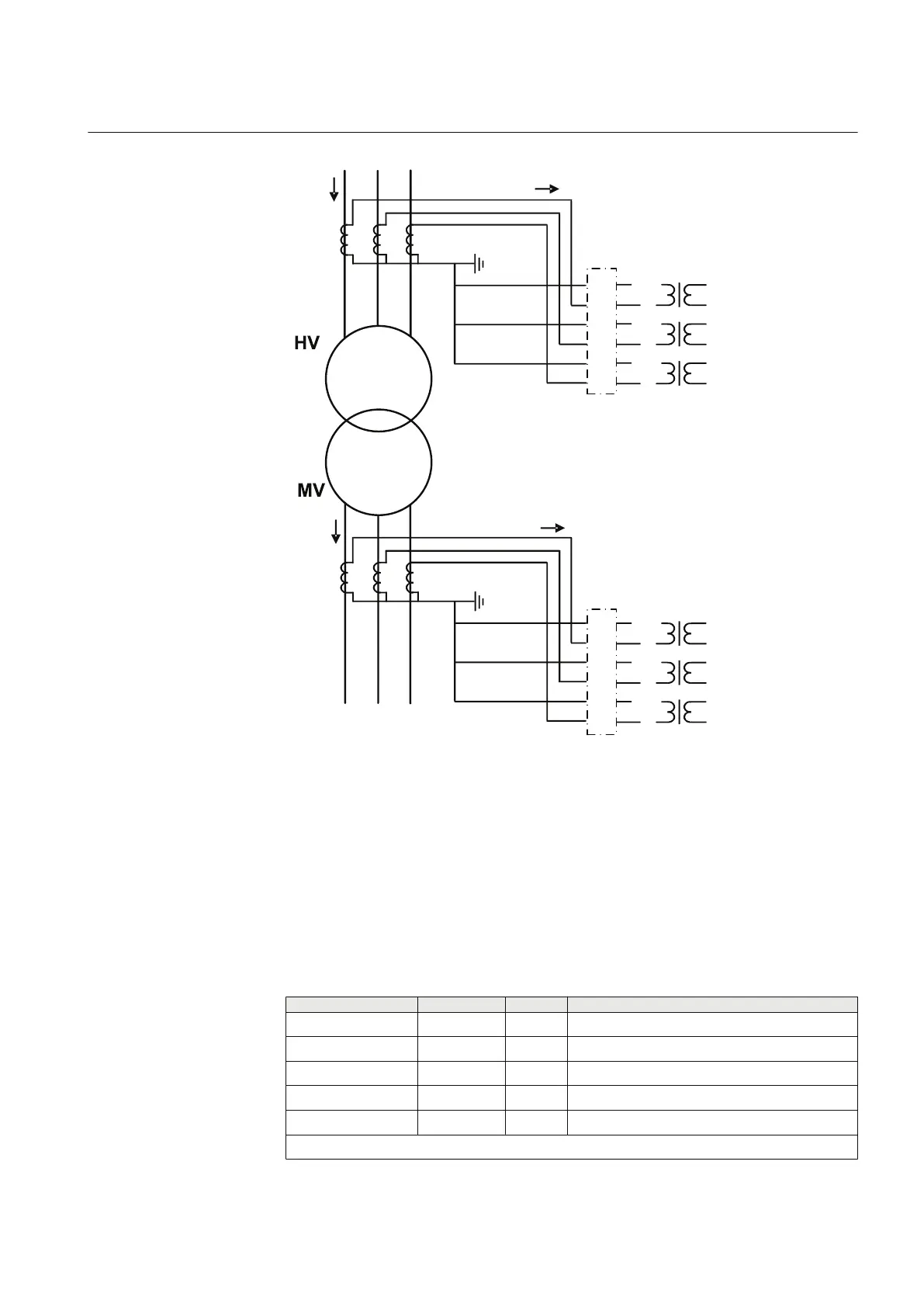
GUID-5E0D15BA-ADA9-4FE0-A85D-5C6E86D7E32B V1 EN
Figure 222: Alternative connection example of current transformers of Type 2
The CT secondary currents often differ from the rated current at the rated load of
the power transformer. The CT transforming ratios can be corrected on both sides
of the power transformer with the CT ratio Cor Wnd 1 and CT ratio Cor Wnd 2
settings.
4.3.2.7 Signals
Table 340: TR2PTDF Input signals
Name
Type Default Description
I_A1 SIGNAL 0 Phase A primary current
I_B1 SIGNAL 0 Phase B primary current
I_C1 SIGNAL 0 Phase C primary current
I_A2 SIGNAL 0 Phase A secondary current
I_B2 SIGNAL 0 Phase B secondary current
Table continues on next page
1YHT530004D05 D Section 4
Protection functions
615 series 417
Technical Manual