22
NHP 304708
Telaio base
Base frame
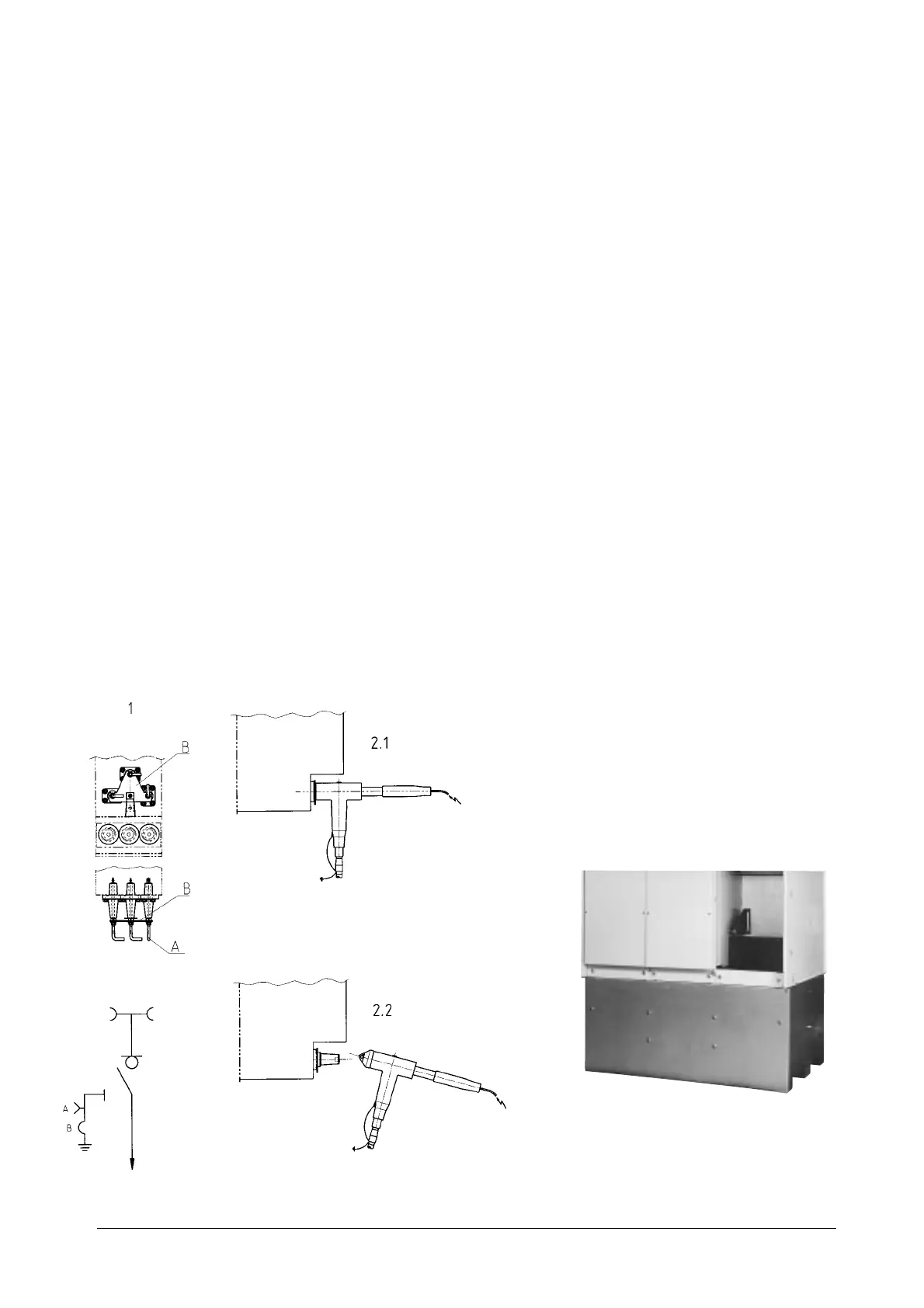
6.6. Cable test
The voltage tests and diagnostic cable tests can be carried out
in two ways.
1. Directly at the test points (A) which may be prepared on the
unit. Proceed as follows: insert the earthing switch and
connect the test apparatus above the fixing points of the
earthing busbar (B). Remove the earthing busbar and
carry out the tests. Before disconnecting the test appara-
tus, remount the earth terminal box.
2. Directly at the cable connectors destined for the cable
voltage tests. Follow the suppliers’ instructions.
2.1. Connector of the connected cable
2.2. Connector of the dismantled cable
6.7. External busbar
The SafeRing and SafePlus switchboards can be fitted with an
external busbar. Please consult the relative instruction manual.
6.8. Arc Suppressor
The Arc Suppressor system can be installed in all the cable
modules of the SafeRing switchboard and in the Dt, De and V
modules of the SafePlus switchboard. The Arc Suppressor
must be ordered with the unit and cannot be installed at a later
date.
Intervention of the Arc Suppressor is signalled by an electric
contact provided in the SF6 gas enclosure and connected to
the terminal box behind the top front panel (an auxiliary feeder
is required for this apparatus).
6.6. Prova cavi
Le prove di tensione e la ricerca diagnostica sui cavi possono
essere effettuate in due modi.
1. Direttamente presso i punti di prova (A) eventualmente
predisposti sull’unità. Procedere come segue: inserire il
sezionatore di terra, e collegare le apparecchiature di
prova sopra i punti di fissaggio della sbarra di terra (B).
Rimuovere la sbarra di terra ed eseguire le prove. Prima di
scollegare le apparecchiature di prova, rimontare la
morsettiera di terra.
2. Direttamente presso i connettori dei cavi destinati alle
prove di tensione dei cavi. Seguire le istruzioni dei fornitori.
2.1. Connettore del cavo collegato
2.2. Connettore del cavo smontato
6.7. Sbarra esterna
I quadri SafeRing e SafePlus possono essere equipaggiati con
una sbarra esterna. Consultare il relativo manuale di istruzioni.
6.8. Sistema di estinzione dell’arco elettrico
Il sistema di estinzione dell’arco elettrico (Arc Suppressor) può
essere installato in tutti i moduli cavi del quadro SafeRing e nei
moduli DT, De e V del quadro SafePlus. L’Arc Suppressor deve
essere ordinato insieme all’unità e non può essere installato
successivamente.
L’intervento del sistema di estinzione dell’arco elettrico è
segnalato da un contatto elettrico predisposto nel contenitore
del gas SF6 e collegato alla morsettiera dietro il pannello
frontale superiore (per tale apparecchiatura, è richiesto un
alimentatore ausiliario).
Fig. 18