27
NHP 304678
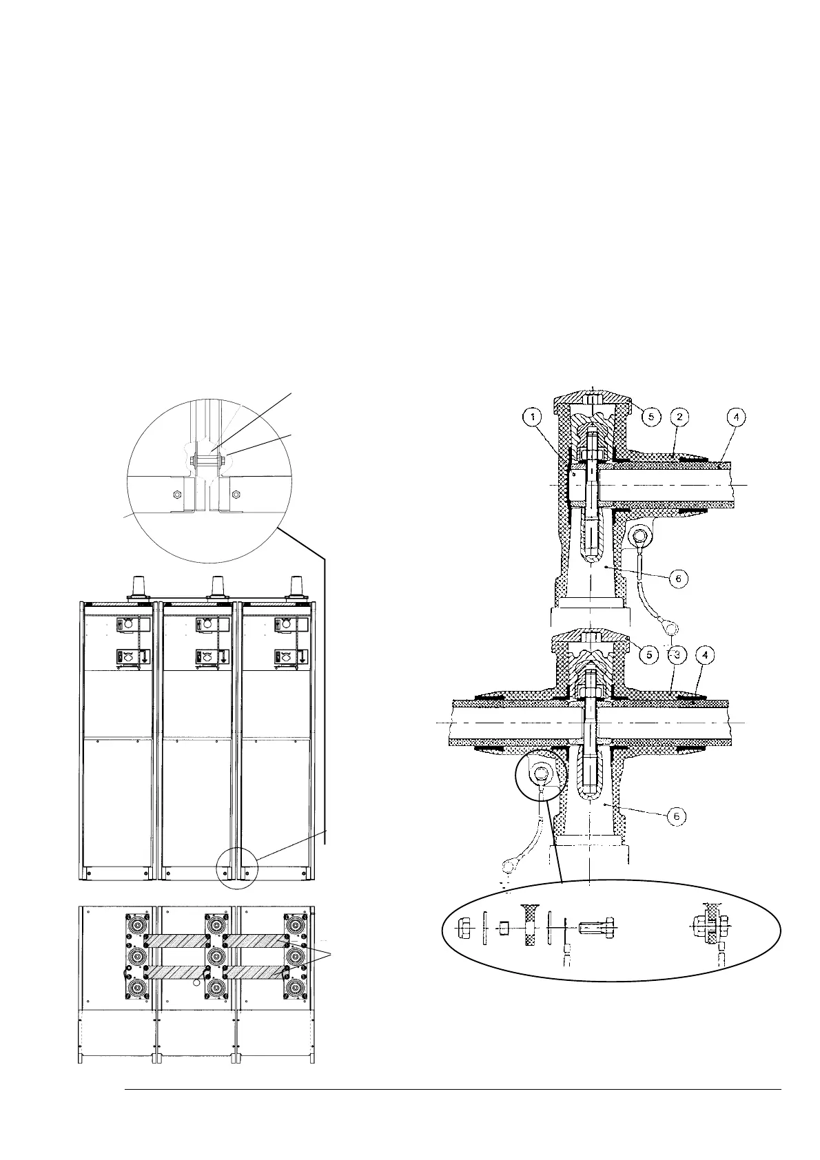
Piastra distanziatrice
Spacer plate
Vite a testa esagonale
Hexagonal-head screw
Spessore
Shim
1. Elemento di contatto
2. Adattatore terminale
3. Adattatore trasversale
4. Sbarra
5. Calotta di copertura
6. Passante
8. Sbarre esterne
8.1. Installazione di moduli o unità
1. Controllare il pavimento prima di installare il modulo/unità.
Verificare che la planarità non sia superiore al 2 per mille.
2. Iniziare con l’installazione di un singolo modulo/unità. Ri-
muovere l’estremità inattiva (l’apparecchiatura non deve
essere in tensione). Se l’apparecchiatura fornita è provvi-
sta di un coperchio sbarra, è necessario rimuoverlo.
3. Collocare il successivo modulo/unità da collegare accanto
al modulo già installato, quindi fissare la distanza con la
piastra distanziatrice e con lo spessore tra le pareti laterali.
8.2. Assemblaggio dell’adattatore trasversa-
le e del terminale schermato.
Sbarra schermata.
Per apparecchiature di media tensione isolate in gas SF6 con
involucro metallico.
8. External busbars
8.1. Installation of modules or units
1. Check the floor before installing the module/unit. Check
that flatness deviation is not more than 2 per thousand.
2. Start installation with a single module/unit. Remove the
inactive end (the apparatus must not be energised). If the
apparatus supplied is fitted with a busbar cover, it must be
removed.
3. Place the next module/unit to be connected beside the
module already installed, then fix the distance with the
spacer plate and with the shim between the side walls.
8.2. Assembly of the transverse adapter and
screened end.
Screened busbar.
For medium voltage SF6 gas-insulated apparatus with metal
enclosure.
1. Contact element
2. End adapter
3. Transverse adapter
4. Busbar
5. Covering cap
6. Bushing
Fig. 21