Operation Manual / TPS48-D/E.. - TPS61-D/E..
Installing the turbocharger
Page 90
© Copyright 2016 ABB. All rights reserved.
September 2016 HZTL2410_EN Revision E
Installing the turbocharger
7.4
Remove covers from the oil connections.
Visually inspect the O-ring gaskets of the oil intake and drain pipe (the
O-ring gaskets on the engine side are not supplied by ABB Turbo Sys-
tems).
**) When the turbocharger is mounted on the engine support, the bolt
threads and screw heads must be lightly oiled (assumed friction coeffi-
cient µ = 0.12 for tightening torque)
Through hole in
bearing casing
[mm]
Strength class
in acc. with
DIN/ISO 898
TPS48 17 M16 230 10.9/12.9
TPS52 21 M20 455 10.9/12.9
TPS57 21 M20 455 10.9/12.9
TPS61 25 M24 780 10.9/12.9
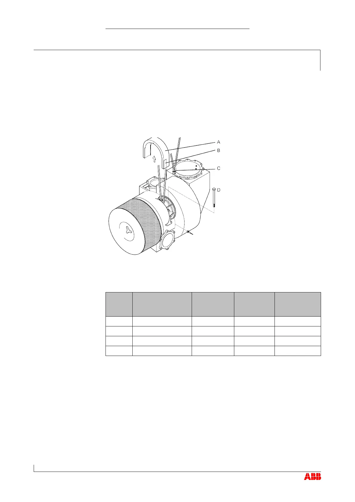
Attach lifting gear to bearing casing.
If a gas outlet bend is present, sling lifting gear around it or secure it to
the lifting gear with a swivel lifting eye (C) (see also section Transport /
Weights).
Lift turbocharger, place on bracket and align.
Tighten fixing screws (D) to the bearing casing in accordance with the
table above.
Attach all gas, water and air lines in accordance with the enginebuild-
er's instructions.
 Loading...