VortexMaster FSV430, FSV450 SwirlMaster FSS430, FSS450 | CI/FSV/FSS/430/450-EN Rev. G 27
3. Use the appropriate screws for the holes.
4. Slightly grease the threaded nuts.
5. Tighten the nuts in a crosswise manner as shown in the
figure. First tighten the nuts to approx. 50 % of the
maximum torque, then to 80 %, and finally a third time to
the maximum torque.
NOTICE
Torques for screws depend on temperature, pressure, screw
and gasket materials. The relevant applicable regulations
must be taken into consideration.
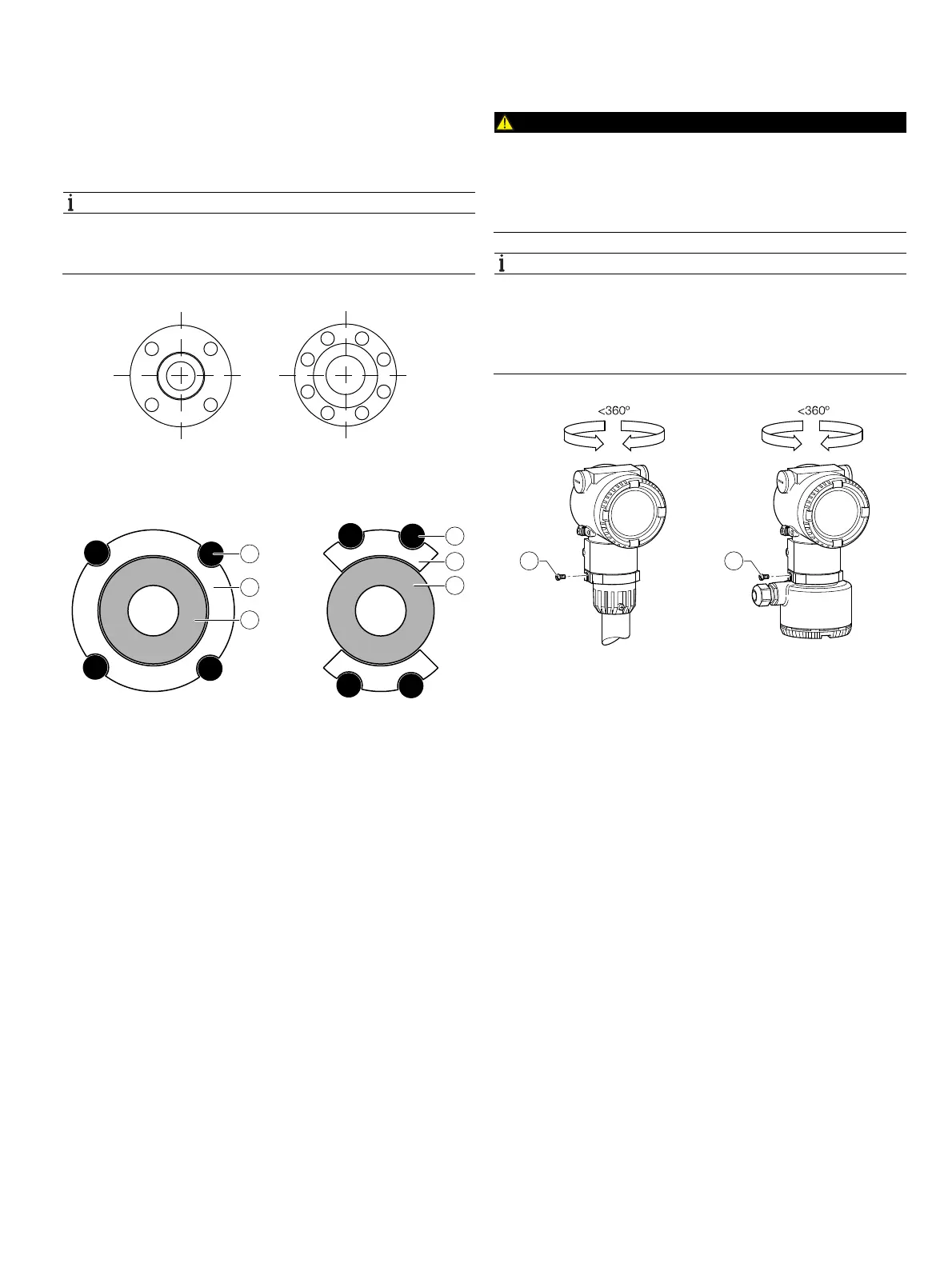
Fig. 24: Tightening sequence for the flange screws
5.4.1 Centering the wafer type design
Fig. 25: Centering the wafer type design with the ring or segment
1 Bolt 2 Centering ring 3 Meter tube (wafer type)
4 Centering segment
Wafer type devices (FV400 only) are centered via the outside
diameter of the flowmeter sensor body with the corresponding
bolts.
Depending on the nominal pressure rating, sleeves for the
bolts, a centering ring (up to DN 80 [3"]) or segments can be
ordered as additional accessories.
5.4.2 Adjusting the transmitter position
Rotating the transmitter housing
DANGER
Risk of explosion!
When the screws for the transmitter housing are loosened,
the explosion protection is suspended.
Tighten all screws for the transmitter housing prior to
commissioning.
NOTICE
Damage to components!
— The transmitter housing must not be lifted without pulling
out the cable, otherwise the cable can tear off
— The transmitter housing must not be rotated more than
360 degrees
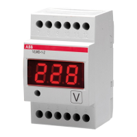
Fig. 26: Rotating the transmitter housing
1 Locking screw
1. Unscrew the locking screw on the transmitter housing with
a 4 mm Allen key.
2. Rotate the transmitter housing in the direction required.
3. Tighten the locking screw.
G11726
1
2
7
8
5
3
4
6
1
2
3
4
G11763
1
2
3
1
4
3
G11764
11