32 CI/FSV/FSS/430/450-EN Rev. G | VortexMaster FSV430, FSV450 SwirlMaster FSS430, FSS450
The possible lead length depends on the total capacity and
the total resistance and can be estimated based on the
following formula.
L =
65 x 106
–
Ci + 10000
R x C C
L Lead length is meters
R Total resistance in Ω
C Lead capacity
C
i
Maximum internal capacity in pF of the HART field devices in the
circuit
Avoid installing the cable together with other power leads (with
inductive load, etc.), as well as the vicinity to large electrical
installations.
The HART handheld terminal can be connected to any
connection point in the circuit if a resistance of at least 250 Ω
is present in the circuit. If there is resistance of less than 250
Ω, an additional resistor must be provided to enable
communication. The handheld terminal is connected between
the resistor and transmitter, not between the resistor and the
power supply.
5.6.5 Devices with Modbus communication
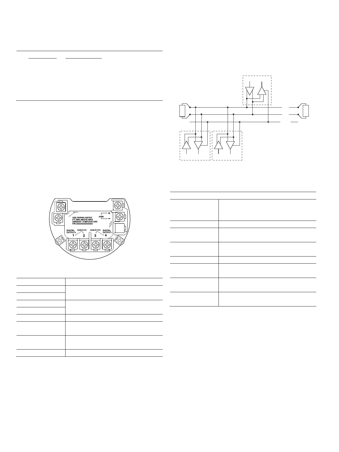
Fig. 34: Terminals
Terminal Function / comment
PWR + Power supply
PWR -
A (+) Modbus interface RS485
B (-)
DIGITAL OUTPUT 1+ Digital output, positive pole
DIGITAL OUTPUT 2 Bridge after terminal 1+, NAMUR output
deactivated
DIGITAL OUTPUT 3 Bridge after terminal 4-, NAMUR output
activated
DIGITAL OUTPUT 4- Digital output, negative pole
Modbus communication
Using the Modbus protocol allows devices made by different
manufacturers to exchange information via the same
communication bus, without the need for any special interface
devices to be used.
Up to 32 devices can be connected on one Modbus line. The
Modbus network can be expanded using repeaters.
Fig. 35: Modbus network (example)
1 Modbus master 2 Terminating resistor 3 Modbus slave 1
4 Modbus slave n … 32
Modbus interface
Configuration Via the Modbus interface in connection with
Asset Vision Basic (DAT200) and a
corresponding Device Type Manager (DTM)
Transmission Modbus RTU - RS485 serial connection
Baud rate 1200, 2400, 4800, 9600 bps
Factory setting: 9600 bps
Parity None, even, odd
Factory setting: none
Typical response time < 100 milliseconds
Response Delay Time
0 ... 200 milliseconds
Factory setting: 50 milliseconds
Device address
1 ... 247
Factory setting: 247
Register address
offset
One base, Zero base
Factory setting: One base
G11946
COMM.
A(+)
B(-)
SURGE
INSIDE
120 Ω
120 Ω
D
R
D
R
D
R
A
B
GND
G11603
1
2
3
4
2