VortexMaster FSV430, FSV450 SwirlMaster FSS430, FSS450 | CI/FSV/FSS/430/450-EN Rev. G 33
Cable specification
The maximum permissible length depends on the baud rate,
the cable (diameter, capacity and surge impedance), the
number of loads in the device chain, and the network
configuration (2-core or 4-core).
— At a baud rate of 9600 and with a conductor cross section
of at least 0.14 mm
2
(AWG 26), the maximum length is
1000 m (3280 ft).
— If a 4-core cable is used in a 2-wire system, the maximum
length must be halved.
— The spur lines must be short (maximum of 20 m [66 ft]).
— When using a distributor with "n" connections, the
maximum length of each branch is calculated as follows:
40 m (131 ft) divided by "n".
The maximum cable length depends on the type of cable
used. The following standard values apply:
— Up to 6 m (20 ft): cable with standard shielding or twisted-
pair cable.
— Up to 300 m (984 ft): double twisted-pair cable with
overall foil shielding and integrated earth cable.
— Up to 1200 m (3937 ft): double twisted-pair cable with
individual foil shielding and integrated earth cables.
Example: Belden 9729 or equivalent cable.
A category 5 cable can be used for Modbus RS485 up to a
maximum length of 600 m (1968 ft). For the symmetrical pairs
in RS485 systems, a surge impedance of more than 100 Ω is
preferred, especially at a baud rate of 19,200 and above.
5.6.6 Electrical data for inputs and outputs
Power supply
Devices with HART communication
Terminals PWR/COMM + / PWR/COMM –
Supply voltage 12 ... 42 V DC
Residual ripple Maximum 5 % or Uss = ±1.5 V
Power consumption < 1 W
Devices with Modbus communication
Terminals PWR + / PWR –
Supply voltage 9 ... 30 V DC
Residual ripple Maximum 5 % or Uss = ±1.5 V
Power consumption < 1 W
Uss Peak-to-peak value of voltage
Current output / HART output
Only for devices with HART communication.
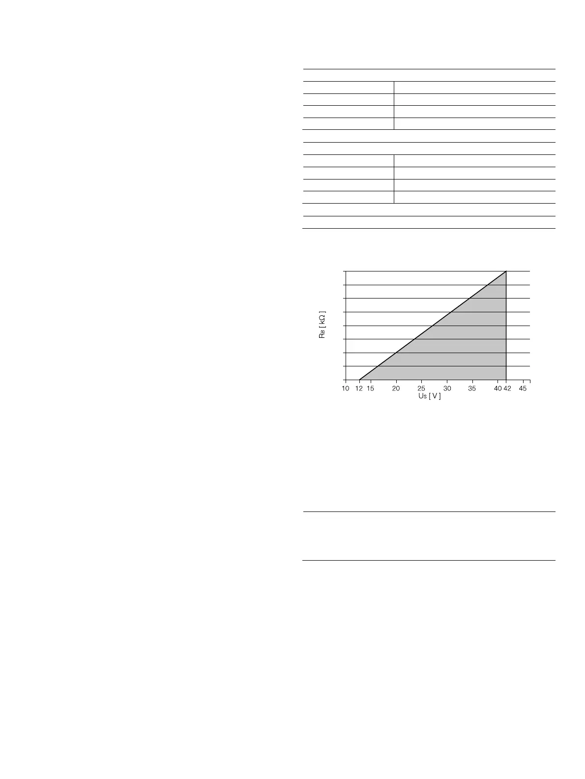
Fig. 36: Load diagram of current output; load depending on supply
voltage
Terminals: PWR/COMM + / PWR/COMM –
In HART communication, the smallest load is R
B
= 250 Ω.
The load R
B
is calculated as a function of the available supply
voltage U
S
and the selected signal current I
B
as follows:
R
B S
= U
B
/ I
R
B
Load resistance
U
S
Supply voltage
I
B
Signalstrom
G11769
1,6
1,4
1,2
1,0
0,8
0,6
0,4
0,2
0