38 CI/FSV/FSS/430/450-EN Rev. G | VortexMaster FSV430, FSV450 SwirlMaster FSS430, FSS450
6 Commissioning
6.1 Safety instructions
DANGER
Danger of explosion if the device is operated with the
transmitter housing or terminal box open!
Before opening the transmitter housing or the terminal box,
note the following points:
— Check that a valid fire permit is available.
— Make sure that there is no explosion hazard.
— Before opening the device, switch off the power supply
and wait for t > 2 minutes.
CAUTION
Risk of burns due to hot measuring media.
The device surface temperature may exceed 70 °C (158 °F),
depending on the measuring medium temperature!
Before starting work on the device, make sure that it has
cooled sufficiently.
6.2 Checks prior to commissioning
The following points must be checked before commissioning:
— The power supply must be switched off.
— The power supply must match the information on the
name plate.
— The wiring must be correct in accordance with the chapter
titled "Electrical connections" on page 29.
— The earthing must correct in accordance with the chapter
titled "Grounding" on page 30.
— The ambient conditions must meet the requirements set
out in the technical data.
— The sensor must be installed at a location largely free of
vibrations.
— The housing cover and its safety locking device must be
sealed before switching on the power supply.
— For devices with a remote mount design, ensure that the
sensor and transmitter are assigned correctly.
6.2.1 Configuration of the outputs
Current output 4 ... 20 mA / HART
In the factory setting, the flow signal is emitted via the current
output of 4 ... 20 mA. Alternatively, the temperature signal can
be assigned to the current output.
Digital output
It is possible to use software to configure the optional digital
output as an alarm, frequency or pulse output.
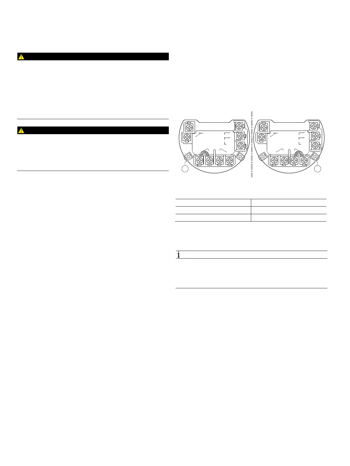
It is possible to use a bridge to configure the digital output as
an optoelectronic coupler output or a NAMUR output.
Fig. 43: Hardware configuration of the digital output
1 Bridge
Output configuration Bridge
Optoelectronic coupler output 1—2
NAMUR output 3—4
In the factory setting, the output is configured as an
optoelectronic coupler output.
NOTICE
The type of protection of the outputs remains unchanged,
regardless of the output configuration.
The devices connected to the digital output must conform to
the current regulations for explosion protection.
G11777
+
–
1
23
4
USE WIRING RATED
5ºC MIN ABOVE MAX
AMBIENT TEMPERATURE
P/N:XXXXXXXXXXXX
DIGITAL
OUTPUT+
DIGITAL
OUTPUT–
PWR / COMM.
TEST
EXT
METER+
+
–
ANALOG INPUT
NAMUR-YES
NAMUR-NO
+
–
1
23
4
USE WIRING RATED
5ºC MIN ABOVE MAX
AMBIENT TEMPERATURE
P/N:XXXXXXXXXXXX
DIGITAL
OUTPUT+
DIGITAL
OUTPUT–
PWR / COMM.
TEST
EXT
METER+
+
–
ANALOG INPUT
NAMUR-YES
NAMUR-NO
A
B
1 1