30 CI/FSV/FSS/430/450-EN Rev. G | VortexMaster FSV430, FSV450 SwirlMaster FSS430, FSS450
5.6.2 Cable entries
The electrical connection is made via cable entries with a
1/2" NPT or M20 x 1.5 thread.
Cable entries with an M20 x 1.5 thread
Devices with an M20 x 1.5 thread are supplied with factory-
installed cable glands and sealing plugs.
Cable entries with a 1/2" NPT thread
The supplied transport sealing plugs do not have IP rating 4X /
IP67 and are not approved for use in potentially explosive
atmospheres.
The transport sealing plugs must be replaced with suitable
cable glands or sealing plugs during device installation.
When selecting the cable glands or sealing plugs, make sure
they have the required IP rating and explosion protection!
To offer IP rating 4X / IP67, the cable glands / sealing plugs
must be screwed in using a suitable sealing compound.
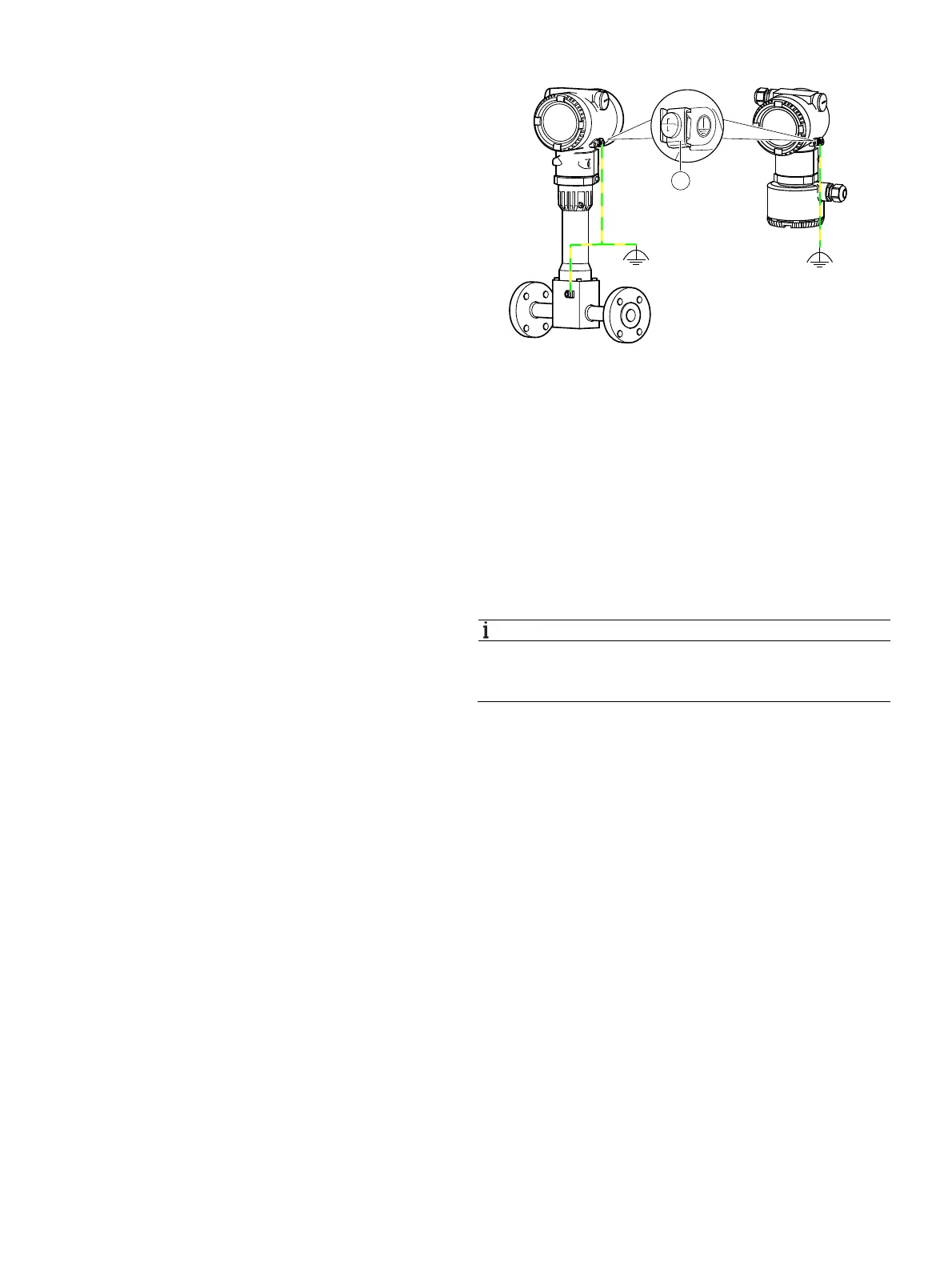
5.6.3 Grounding
Fig. 30: Grounding terminals
1 Integral mount design and sensor in remote design
2 Transmitter in remote mount design 3 Grounding terminal
For the grounding (PE) of the transmitter or the connection of
a protective earth, a connection is available both on the
exterior of the housing and in the connection space. Both
connections must be galvanically connected to one another.
These connection points can be used if grounding or the
connection of a protective conductor is prescribed by national
regulations for the selected type of supply or the type of
protection used.
NOTICE
In order to avoid external influences on the measurement, it
is imperative to ensure that the transmitter and the separate
flowmeter sensor are properly grounded.
1. Loosen the screw terminal on the transmitter housing or
on the housing of the VortexMaster / SwirlMaster.
2. Insert the forked cable lug for functional grounding
between the two metal tabs and into the loosened
terminal.
3. Tighten the screw terminal.
G11774
12
3