58 CI/FSV/FSS/430/450-EN Rev. G | VortexMaster FSV430, FSV450 SwirlMaster FSS430, FSS450
7 Operation
7.1 Safety instructions
If there is a chance that safe operation is no longer possible,
take the device out of operation and secure it against
unintended startup.
7.2 Parameterization of the device
The LCD indicator has capacitive operating buttons. These
enable you to control the device through the closed housing
cover.
NOTICE
The transmitter automatically calibrates the capacitive
buttons on a regular basis. If the cover is opened during
operation, the sensitivity of the buttons is firstly increased to
enable operating errors to occur. The button sensitivity will
return to normal during the next automatic calibration.
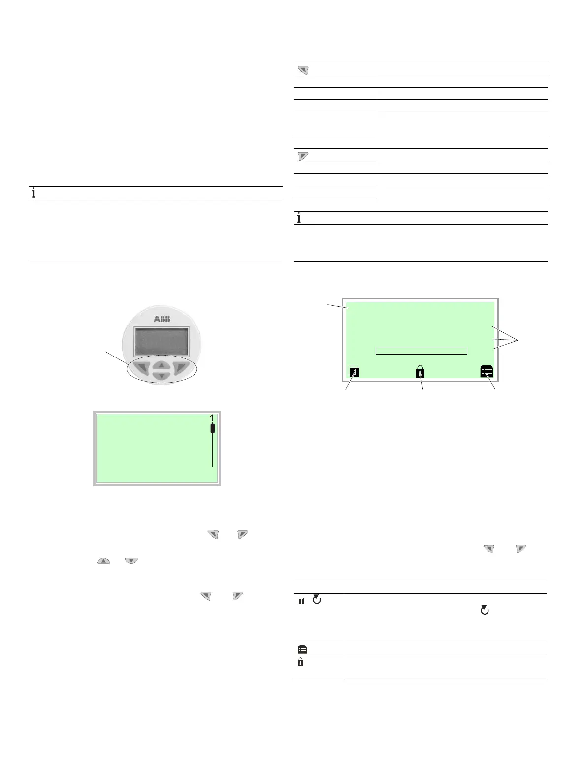
7.2.1 Menu navigation
2
Menu
3
4
Exit Select
Fig. 51: LCD display
1 Operating buttons for menu navigation
2 Menu name display 3 Menu number display
4 Marking to indicate the relative position within the menu
5 Display of the current function of the buttons and
You can use the or operating buttons to browse
through the menu or select a number or character within a
parameter value.
Different functions can be assigned to the and
operating buttons. The function that is currently assigned
5
is shown on the LCD display.
Operating button functions
Meaning
Exit
Exit menu
Back
Go back one submenu
Cancel
Cancel parameter entry
Next
Select the next position for entering numerical
and alphanumeric values
Meaning
Select
Select submenu / parameter
Edit
Edit parameter
OK
Save parameter entered
NOTICE
For a detailed description of the individual parameters and
menus on the configuration level, please refer to chapter
Parameter descriptions in the operating instruction.
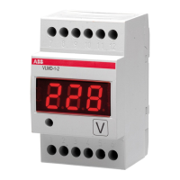
7.2.2 Process display
Fig. 52: Process display (example)
1 Measuring point tagging 2 Current process values
3 "Button function" symbol
4 "Parameterization protected" symbol
The process display appears on the LCD display when the
device is switched on. It shows information about the device
and current process values.
The way in which the current process values are shown can
be adjusted on the configuration level.
The symbols at the bottom of the process display are used to
indicate the functions of the operating buttons and , in
addition to other information.
Symbol Description
/
Call up information level.
When Autoscroll mode is activated, the symbol
appears here and the operator pages are automatically
displayed one after the other.
Call up configuration level.
The device is protected against changes to
parameterization.
M10145-01
1
G11783
Pump 1
1
43
2
3
Qv
T
Qdn
m3/h
°C
0%
0.00
40.322