VortexMaster FSV430, FSV450 SwirlMaster FSS430, FSS450 | CI/FSV/FSS/430/450-EN Rev. G 31
5.6.4 Devices with HART communication
Current output / HART output
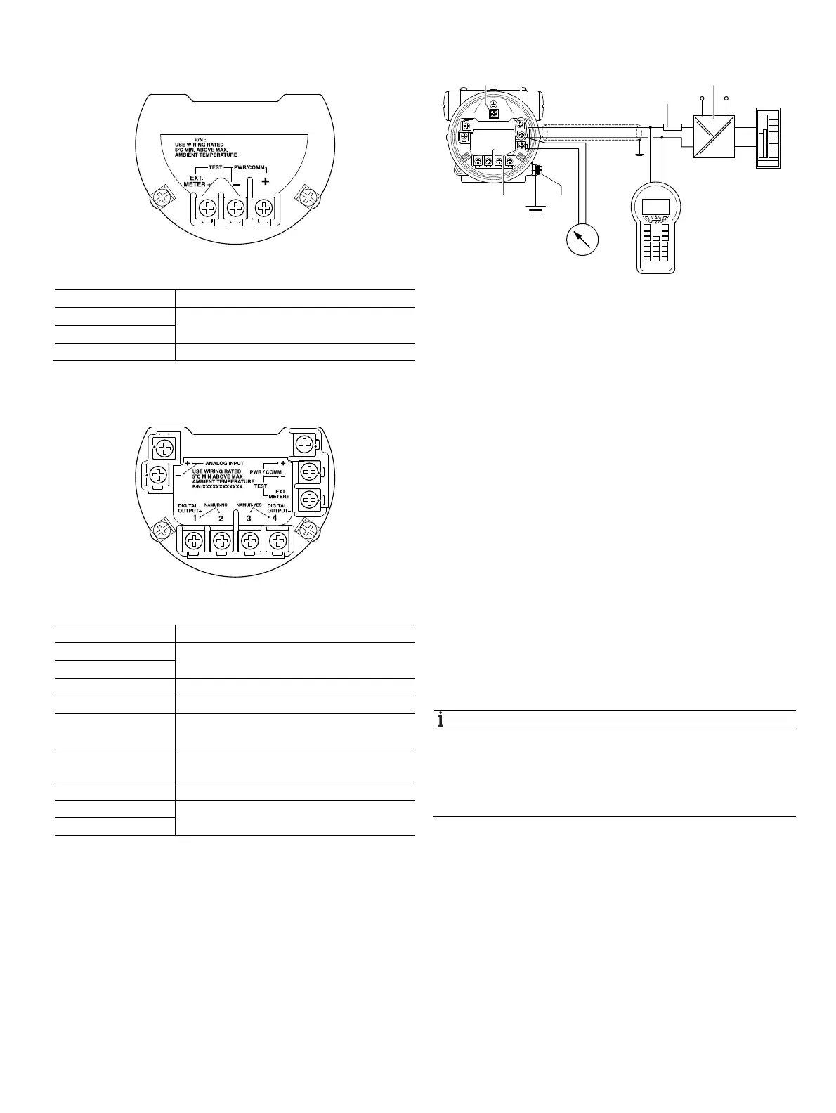
Fig. 31: Terminals
Terminal Function / comment
PWR/COMM + Power supply, current output / HART output
PWR/COMM -
EXT. METER Not assigned
Current output / HART output, digital output and analog
input
Fig. 32: Terminals
Terminal Function / comment
PWR/COMM + Power supply, current output / HART output
PWR/COMM -
EXT. METER + Current output 4 ... 20 mA for external display
DIGITAL OUTPUT 1+ Digital output, positive pole
DIGITAL OUTPUT 2 Bridge after terminal 1+, NAMUR output
deactivated
DIGITAL OUTPUT 3 Bridge after terminal 4-, NAMUR output
activated
DIGITAL OUTPUT 4- Digital output, negative pole
ANALOG INPUT + Analog input 4 ... 20 mA for remote transmitter,
e.g. for temperature, pressure, etc.
ANALOG INPUT -
HART communication
Fig. 33: HART communication (example)
1 Internal earthing terminal 2 Power supply, current output /
HART output 3 Load resistance 4 Power supply / supply isolator
5 PLC / DCS 6 HART Handheld terminal 7 External indicator
8 External earthing terminal 9 Terminal for external indicator
For connecting the signal voltage / supply voltage, twisted
cables with a conductor cross-section of 18 … 22 AWG /
0.8 … 0.35 mm
2
and a maximum length of 1500 m (4921 ft)
must be used. For longer leads a greater cable cross section
is required.
For shielded cables the cable shielding must only be placed on
one side (not on both sides).
For the earthing on the transmitter, the inner terminal with the
corresponding marking can also be used.
The output signal (4 20 mA) and the power supply are
conducted via the same conductor pair.
The transmitter works with a supply voltage between
12 ... 42 V DC. For devices with the type of protection "Ex ia,
intrinsic safety" (FM, CSA, and SAA approval), the supply
voltage must not exceed 30 V DC. In some countries the
maximum supply voltage is limited to lower values. The
permissible supply voltage is specified on the name plate on
the top of the transmitter.
NOTICE
Any configuration changes are saved in sensor memory only
if no HART communication is taking place. To ensure that
changes are safely stored, make sure that HART
communication has ended before disconnecting the device
from the network.
G11766
G11767
G11964
+
–
+
–
–
+
+
–
6
1 2
3
4
5
7
9 8