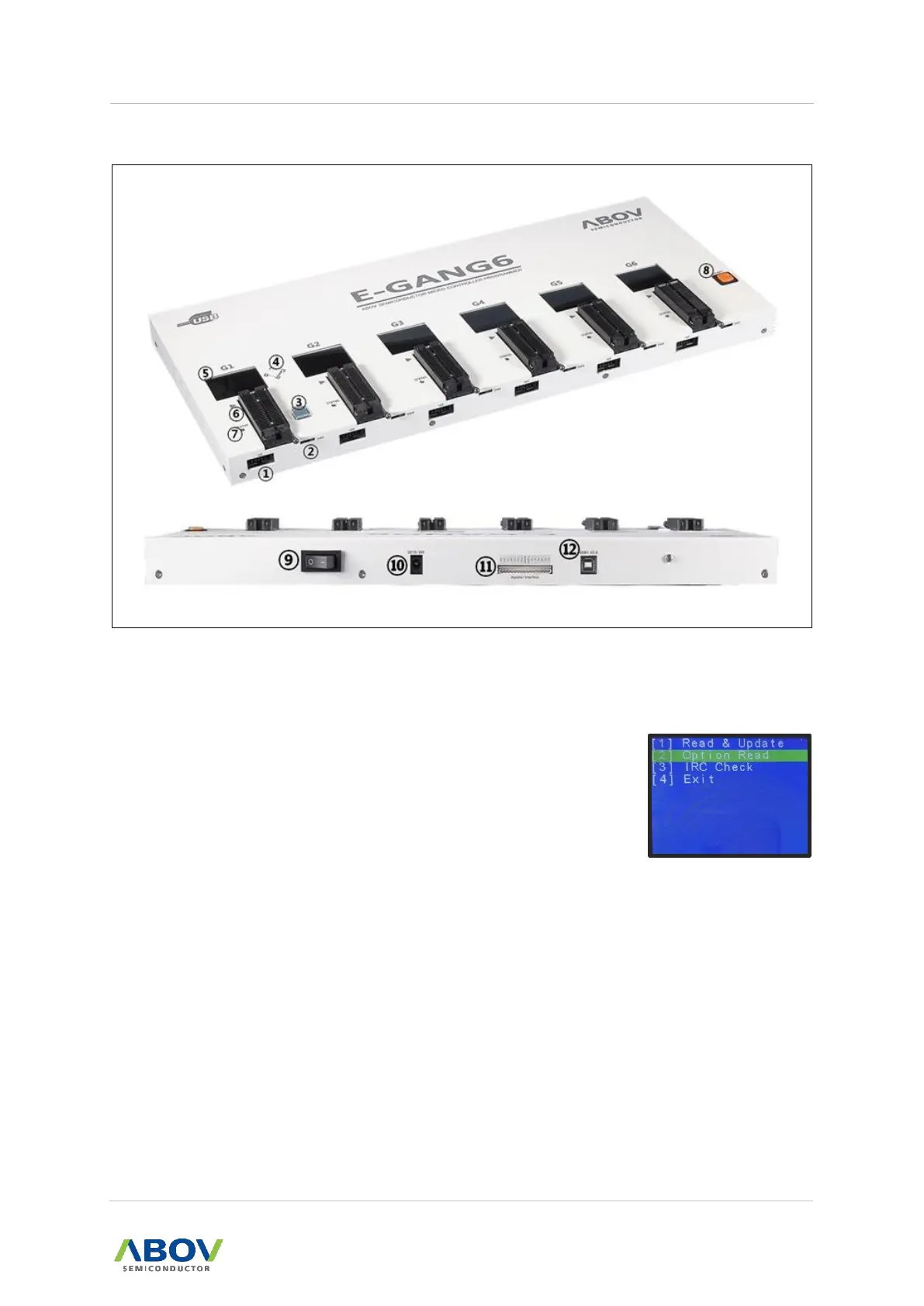
Figure 8. E-GANG6 Top and Side Views for Function Description
① 10-pin IDC connector for In-System Programming (ISP)
② SWD port for firmware update and development purpose (Not for use)
③ A button for programming the target device ‘G1’ (only)
④ A button for reading the target device
⑤ LCD Screen for Information Display:
— Device name, checksum data and options
— PASS/FAIL is shown as a result of programming,
accompanied by error information in the case of failure.
⑥ 40-pin DIP TEXTOOL Socket for gang programming mode:
— Gang4 has four separate sockets.
— Gang6 has six separate sockets.



 To Next Page