4-3Chapter 4: The Magnetic Switch
8) Using the spacer provided in the kit,
position the door magnet as shown in
figure 4.3 and mark where the mounting
holes (7/64”) will be drilled.
9) After you have marked and drilled your
holes, mount the magnet with the 1/8”
spacer in between the magnet and the
door. Important: Remember, if the door
frame is metal you must install the spacer
in between the magnet and the door or
the magnet will lose effectiveness.
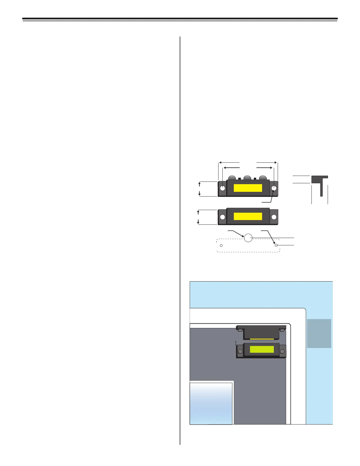
Mounting
To mount the magnetic switch, refer to figure
4.3 and use the following instructions:
1) After choosing your location, following
the hole pattern shown in figure 4.2, drill
two 7/64” (0.109) mounting holes in the
door frame to accommodate the switch.
This size hole also coincides with the
self-tapping screws provided with the
switch. Be careful not to drill these holes
oversize.
2) Drill a 5/16” (0.312) pass-through hole
in the door frame to accommodate the
wire from the LC1400T to the switch.
Important: This hole should be drilled
so the wire will come up just under
the middle screw terminal (N.C.) of the
switch. This hole can be drilled a little
smaller, but not larger. If this hole is
drilled too far out from the body of the
switch, then the switch cover will not
be able to hide this hole. Be sure to “de-
burr” this hole.
3) Fish the 2-conductor/22-gauge wire
through the large hole and strip enough
insulation to make a good connection to
the switch.
4) Connect the red wire to the COM terminal
of the Switch.
5) Connect the black wire to the N.O.
terminal of the switch.
6) Gently guide the excess cable back
through the hole in the frame, while
moving the switch into position over its
mounting holes.
7) While positioning the switch, insert a
mounting screw through each hole and
secure the switch in place with the cover-
side facing away from the door. Be careful
not to pinch the wires when tightening.
Door Frame
1/8” to 3/16”
Door
Door Frame
Door Stop
Switch
Magnet
Switch
mounted
on frame.
Magnet
mounted
on door.
Figure 4.3
Mounting the Magnetic Switch
2.500”
2.100”
0.516”
0.786”
0.5”
0.300”
Ø0.109”
Ø0.156”
Ø0.312”
0.525”
Hole Pattern
Cover
Switch
Magnet
Figure 4.2
Magnetic Switch Dimensions
 Loading...