2-9Chapter 2: The LC1400T
LC1400T Controller
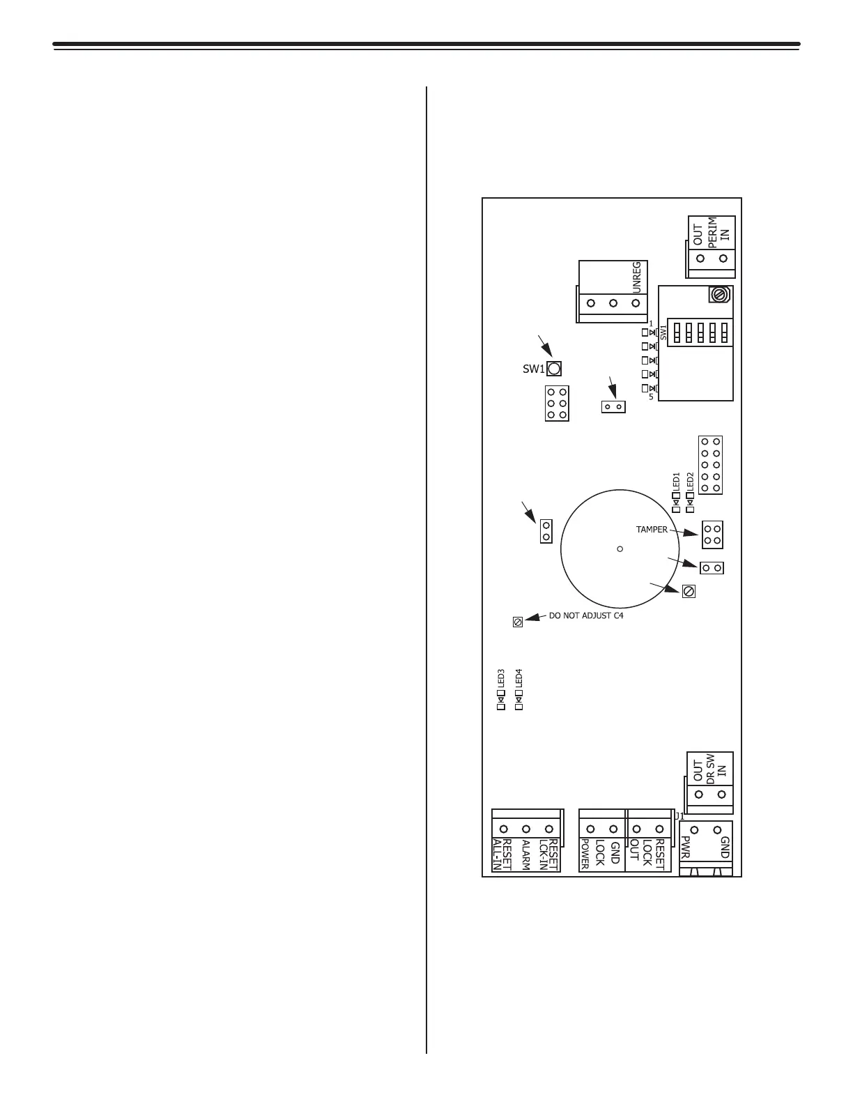
The Circuit Board
• LEDs
• LED Displays
• Jumpers
• Low Frequency Tuners
• Switches
• Tamper Infrared Sensor
• Power Input
• Potentiometers
• Terminals
LEDs
LED1 (Alarm/Error) (Red)
LED2 (Power Indicator) (Green, Solid)
LED3 (Rx Signal Strength)
LED4 (Rx Signal Strength)
LED Displays
LED-X
(Bar Display X-Axis) (Blue)
This Bar Display indicates that the X-axis is
powered and displays its relative Tx Output
level.
Jumpers
JP1
(RS485, Terminating Resistor)
Default position: In
In: Add resistor
Out: Remove resistor
JP2
(Sound Enable)
Default position: In
In: Sound enabled
Out: Sound disabled
JP6
Tuning LED Enable)
Default position: In
In: Tuning LED Enabled
Out: Tuning LED Disabled
Figure 2.9
LC1400T Circuit Board
TX-ANT
C1
J4
J5
JP1
JP2
TB1 TB2
TB3
TB4
VOLUME
R9
IR1
C4
JP6
LF
TUNING
BOARD
TUNING LED
ENABLE
RESET
TERMINATING
JUMPER
PIEZO
ENABLE
PIEZO
VOLUME