60 Chapter 3
Main Unit Disassembly Process
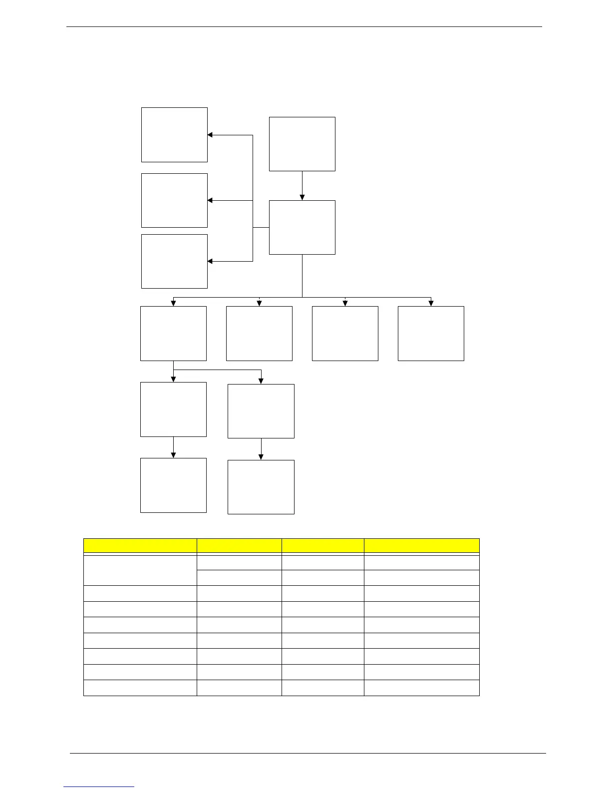
Main Unit Disassembly Flowchart
Screw List
Step Screw Quantity Part No.
Lower Cover M2.5*8 11 86.R4F02.002
M2*3 4 86.R4F02.004
Upper Cover M2.5*5 7 86.R4F02.001
Speaker M2*3 2 86.R4F02.004
Power Board M2*3 1 86.R4F02.004
USB Board M2*3 1 86.R4F02.004
Mainboard M2.5*5 1 86.R4F02.001
Thermal Module M1.98*3 4 86.R4F02.008
LCD Module M2.5*8 4 86.R4F02.002
Remove
Mainboard
Remove
Upper Cover
Remove
Power Board
Remove External
Modules before
proceeding
Remove
Touchpad FFC
Remove
Speaker Module
Remove
CPU
Remove
Thermal Module
Remove
DC-IN Assembly
Remove
LCD Module
Remove
ODD Connector
Board
Remove
Bluetooth Module
Remove
USB Board