Chapter 5 73
Connecting Case Components
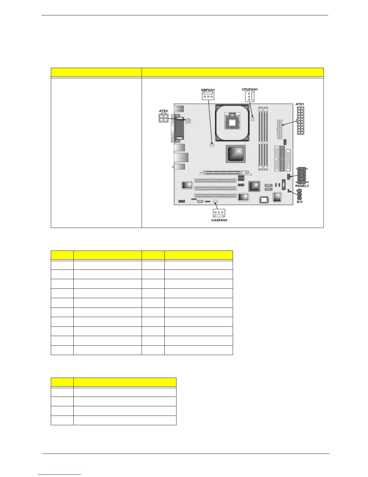
After you have installed the mainboard into a case, you can begin connecting the mainboard components.
Refer to the following:
Description Connector
1. Connect the CPU cooling
fan cable to CPUFAN1.
2. Connect the case cooling
fan connector to
CASFAN1.
3. Connect the Northbridge
cooling fna to NBFAN1.
4. Connect the case LED
cable to SJ1. Connect the
case switches and
indicator LEDs to the
PANEL1.
5. Connect the standard
power supply connector
to ATX1.
6. Connect the Pentium 4
processor auxiliary case
power supply connector
to ATX2.
ATX1: ATX 20-pin Power Connector
Pin Signal Name Pin Signal Name
1 +3.3V 11 +3.3V
2 +3.3V 12 -12V
3 Ground 13 Ground
4 +5V 14 PS NO#
5 Ground 15 Ground
6 +5V 16 Ground
7 Ground 17 Ground
8PWRGD 18+5V
9 +5VSB 19 +5V
10 +12V 20 +5V
ATX2: ATX12V Power Connector
Pin Signal Name
1 +12V
2 +12V
3 Ground
4 Ground