3. POWER ON, CONTROLS AND INDICATORS
NOTICE
Do not turn the amplifier on for at least 2 hours after unpacking it in the room where it
will be used. Pay particular attention when you move it from a very cold into a warm
place - condensation is likely and this could result in damage to the high voltage circuits.
In such a case, wait at least 4 hours. A similar effect can occur after a rapid warming of
the operating room (for instance after switching on a powerful heater in a cold shack).
NOTICE
In order to avoid any damage (not covered by the warranty), check carefully to be
certain that the voltage for which the amplifier is set corresponds to your mains nominal
voltage (see Section 2.2 Line Voltage Selection and Table 2-1 Amplifier individual data).
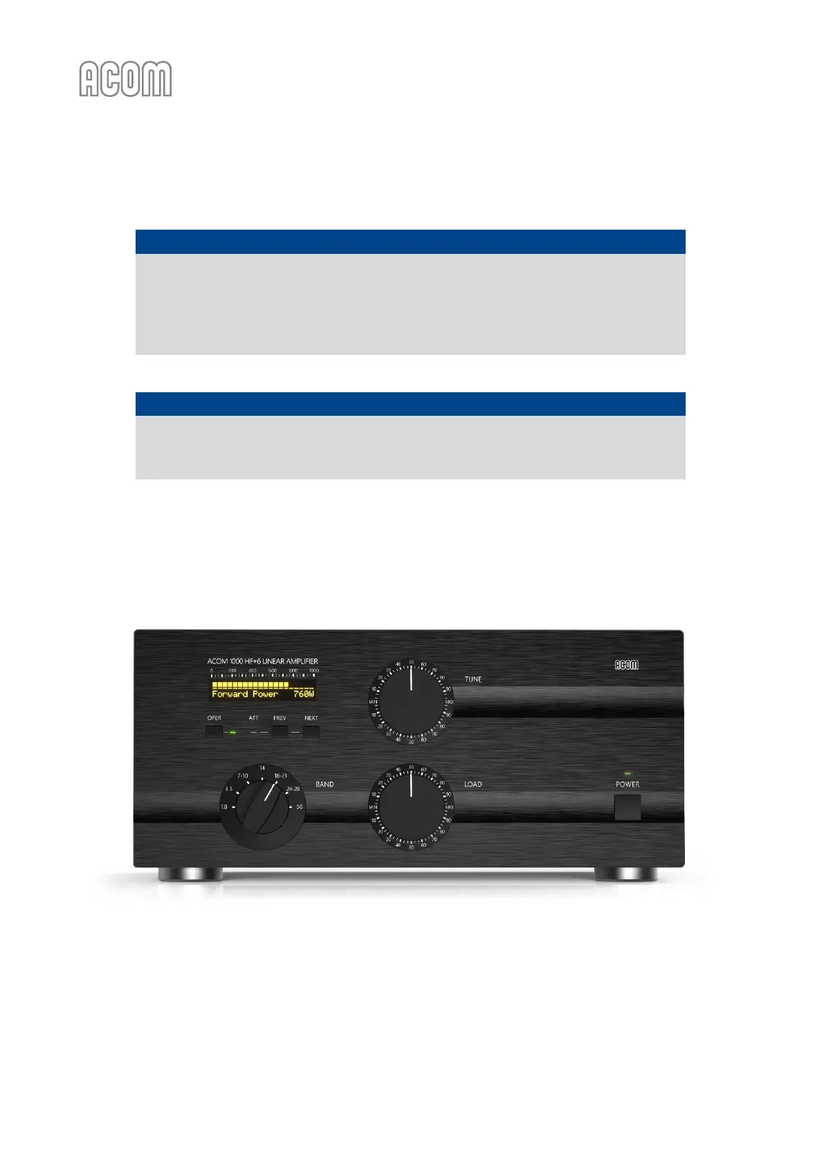
After following all instructions in Section 2 INSTALLATION, you may turn on the main power switch (marked
"LINE") on the rear panel (see Figure 2-1 Rear panel - Connections, Pos. (2)). The LED indicator above the
POWER button (located on the front panel) must light red and "ACOM 1000" will appear on the display
(see Figure 3-1 Front panel - Display and Controls).
Figure 3-1 Front panel - Display and Controls
Figure 3-1 Front panel - Display and Controls
You will note that the upper line of the display always reads the peak forward power, even in STBY mode.
The scale resolution is 10 W per bar. Note also that levels below 20 W may be not detected.
In this position (called OFF LINE hereafter), only the micro-controller is operational, while the amplifier
itself is still turned off (the tube is not powered at all).