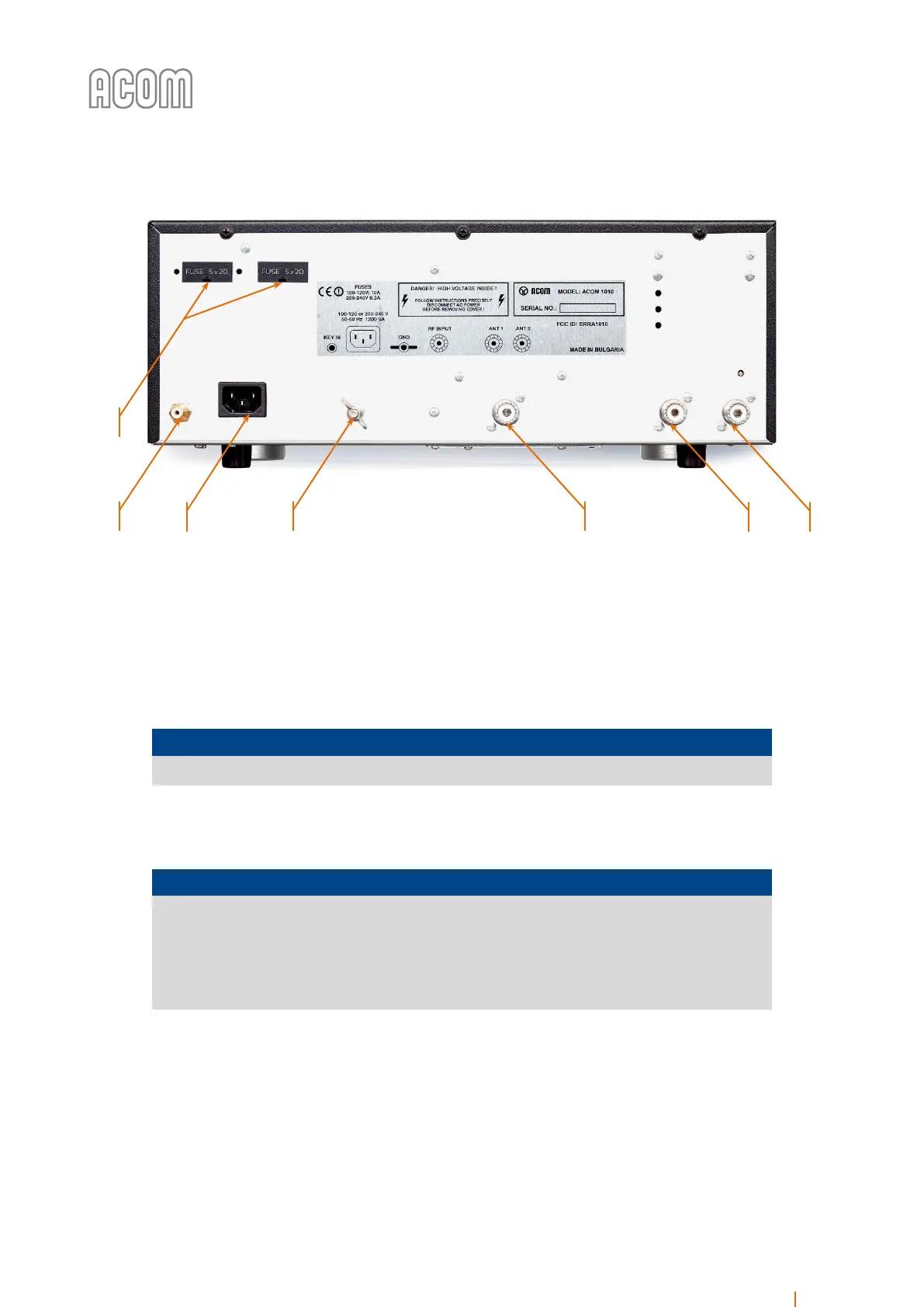
Figure 2-1 Rear panel - Connections
Figure 2-1 Rear panel - Connections
b) RF INPUT socket
Connect a suitable coaxial cable from the transceiver output to the amplifier RF INPUT SO-239 socket (see
Figure 2-1 Rear panel - Connections, Pos. (b)), using PL-259 plug.
NOTICE
In order to avoid a damage, turn off your transceiver's internal antenna tuner.
c) ANT1 and ANT2 sockets
NOTICE
If this is the first time you will use a power amplifier in your station, pay attention to the
coaxial cable type from the amplifier's output to the antenna. It must handle the
increased power safely, particularly on the 10-meter band. It is suggested that, at a
minimum, RG8X (including RG8MINI, RK50-4-11, RK50-4-13) or, even better, RG213
(including RK50-7-11) coaxial cable be used.
Connect a suitable coaxial cable with a PL-259 plug from the amplifier output ANT1 or ANT2 (see Figure 2-1
Rear panel - Connections, Pos. (c)) to the antenna selector or tuner, or to the antenna for the respective
frequency band.