Copyright © 2016 Access Control Technology Ltd. Part No. 18-00099 Issue 1.0
17
ACTpro 1520e and ACTpro 1500e Operating & Installation Instructions
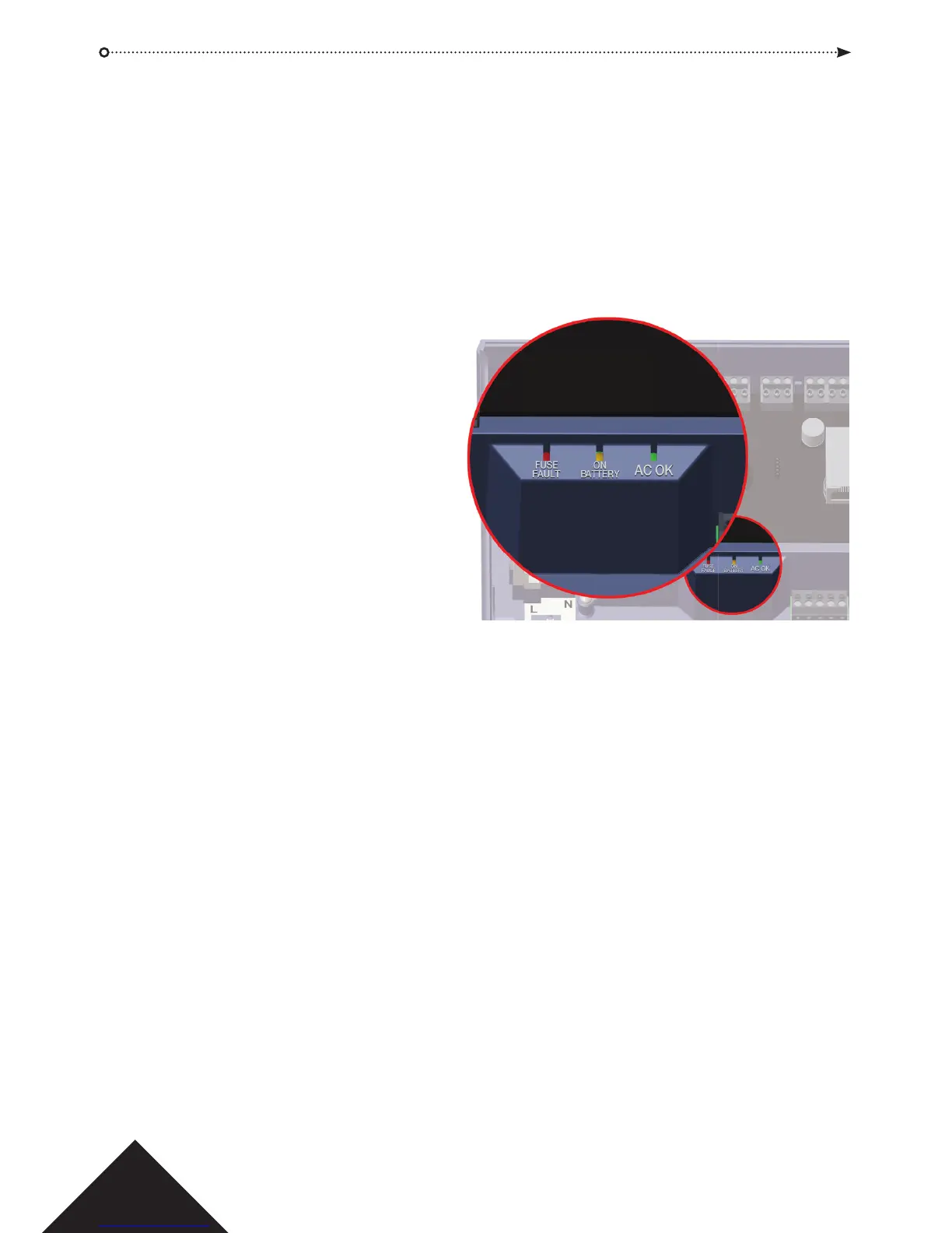
LED indicators
Green - AC OK Indicates that the AC Mains is within speci cation.
Amber – ON BATTERY Indicates that the battery is supplying the output voltage.
Red - FUSE FAULT Indicates electronic output shutdown fuse is active and
that no power is being supplied to the load.
The maximum current that the PSU can
guarantee is 1.5A plus 0.5A for battery
charging. Beyond this the fuse will trip
and the LED will stay on until the load is
fully disconnected.
Once the load has been disconnected,
remove devices to reduce the current
demand below 1.5A.
It is important to calculate the power
budget adequately. Please refer to the
section on the following page titled
‘Power Budget’ for more information.
Installation Instructions
The ACTpro 1520e/1500e Controllers are for indoor installation only and must be installed
as permanently connected equipment.
An external mains disconnect device must be tted. Before installation ensure that the
mains supply to the controller is disconnected.
Mains power should be connected to ACTpro Controllers by a licensed electrician in
accordance with local/national codes.
Mounting
Mount the controller directly on to the wall with the supplied screws.
The keyed mounting hole should be screwed rst to the wall to aid the mounting.
The unit should be installed in a ventilated area that allows for accessibility after
installation.