Copyright © 2016 Access Control Technology Ltd. Part No. 18-00099 Issue 1.0
ACTpro 1520e and ACTpro 1500e Operating & Installation Instructions
20
Steps to Program the ACTpro Controller for ARM/DISARM
1. Complete the wiring in the diagram for the door that the system will be Arm/Disarmed from.
2. “ACT Install | Advanced Setup | doors | <door#> | AUX Relay” enable ‘Arm Intruder Panel’.
3. If the Alarm Panel provides a signal to indicate it’s arm/disarm status then
“ACT Install | Advanced Setup | doors | <door#> | Operation” enable ‘Intruder Panel’.
4. From “ACTmanage | Manage | Users” select the users that will be allowed to arm and disarm
the panel and set the option “ARM/DISARM”. Make sure the user is enabled.
5. “ACT Manage | Manage | Users | <user> | Options” and enable ‘Arm/Disarm’.
6. The User can arm the system at the reader by rst pressing the "tick" key followed by presentation
of a card. Once the intruder panel is armed (as monitored by the AUX I PIN) the Door will lock.
7. Disarming is achieved by again pressing the "tick" key and presenting the Card.
NC
C
NO
Intruder
Alarm Panel
NC
C
NO
NC
C
NO
OP3
OP2
0V
AUX I
DC
PB
A
B
0V
A
B
0V
A
B
OV
0V
+12V
MAINS
PRESENT
B/GL
TAMP
IN OUT
2-16 DOORS 17-32 CTRL NW
1520e
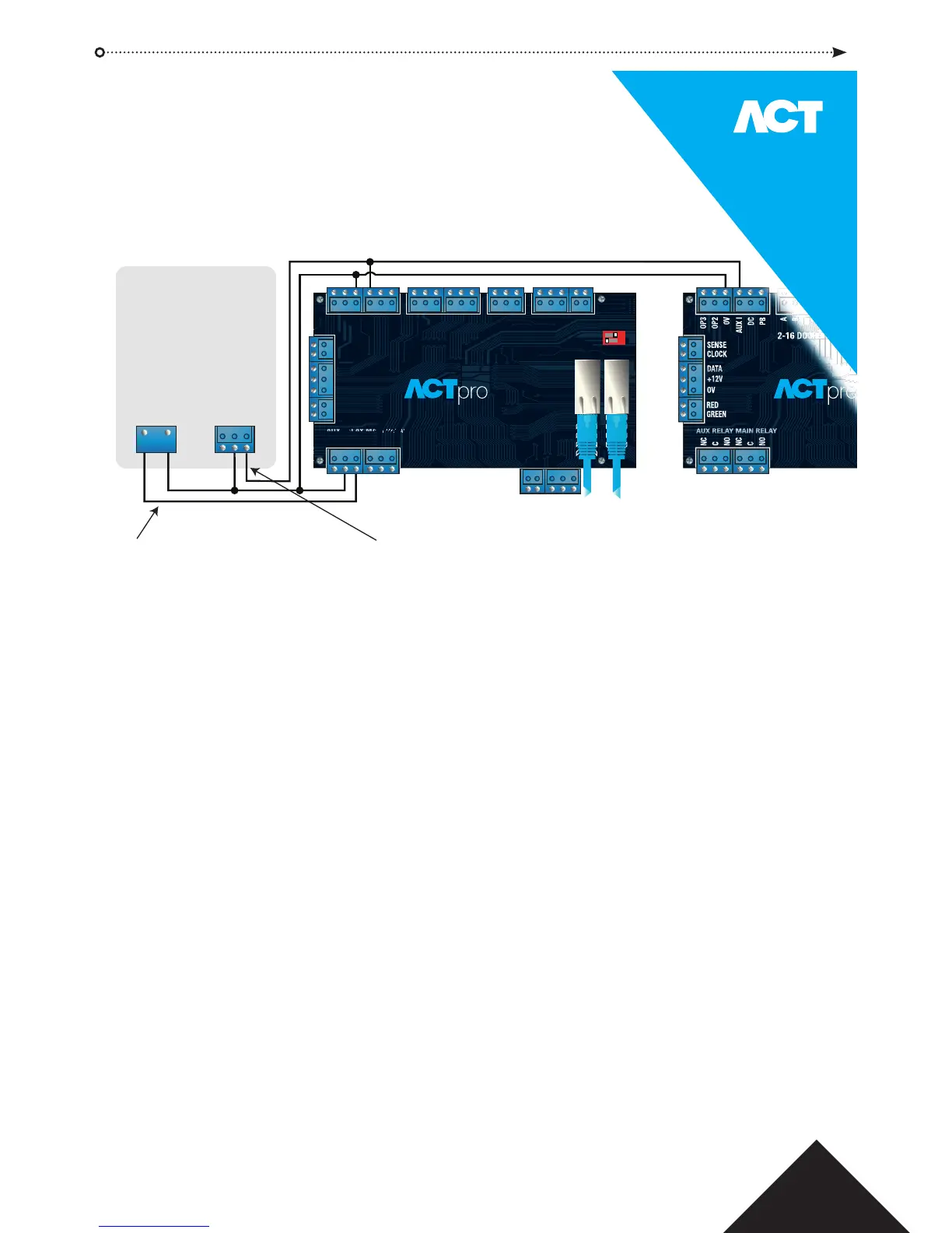
NOTE: If multiple doors are required to lock when the intruder panel is armed then it is required that each door monitors the alarm status.
If the intruder panel is not being monitored then only the door that is wired to control the intruder panel will lock.
Connect AUX Relay output from the controller
to arm input on alarm panel. The AUX relay can
be set to pulse or toggle. Toggle by
programming the AUX Relay time to zero.
Optional signal from the alarm panel to indicate armed or disarmed status.
If 0V is connected to AUX Input, the panel is armed.
Input 0V
To arm/disarm intruder panel.
1 2
DHCP
DEFAULT
ON
OFF
14.0 Intruder Panel Wiring Diagram