7. Art. Description MAGNET HOLDER PLATE
. (Not found? Move to the next step.)
Verify x-position and y-position. These
coordinates correspond to the MAGNET HOLDER PLATE bottom left corner. Identify the glass upper edge considering
your glass height starting from your reference point. From the upper edge left corner moving to the right on the horizontal
axe identify the x-position of the MAGNET HOLDER PLATE.
EXPERT TIPS. Before proceeding consider your crystal position. For recessed installation the drilling points must be
positioned at 30 mm from the back of your crystal (25 mm for MAGNET HOLDER PLATE 150, 15 cm width). For flush
installation consider: Glass Depth + 30 mm (25 mm for MAGNET HOLDER PLATE 150, 15 cm width). Marginal inaccuracy
can be corrected with the long slots in the MAGNET HOLDER PLATE.
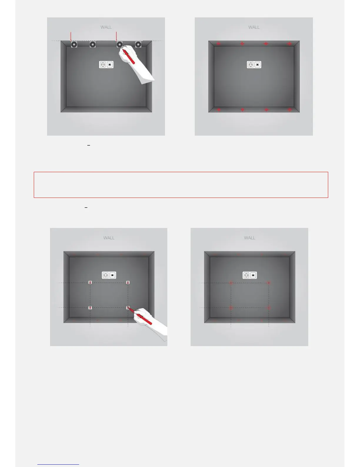
8. Art. Description MAGNET HOLDER PLATE
. (Not found? Move to the next step.)
Position the MAGNET HOLDER PLATE and mark
the drilling points with a pencil. Caution: you might have more MAGNET HOLDER PLATEs. Repeat the procedure for each
one of them.
9. Art. Description - HOLDING ANGLE
. (Not found? Move to the next step.)
Verify x-position and y-position. These coordinates
correspond to the HOLDING ANGLE middle screw drilling point. Start from the reference point moving to the right on the
horizontal axe and mark the point (y-position). Plot a vertical line verifying vertical alignment using the level. Measure and
mark the drilling point on this line accordingly (y-position). Caution: you must have 4 HOLDING ANGLES. Repeat the
procedure for each one of them.
EXPERT TIPS. Before proceeding verify the point horizontal alignment using the level. You can also plot an additional
horizontal line and verify its distance from the crystal upper and bottom edge.