17
This transceiver contains a EEPROM to retain 81 memory
channels(CALL channel included).
The data listed below can be stored in each memory channel.
5-4 MEMORY
5-4-1 Memory Channels
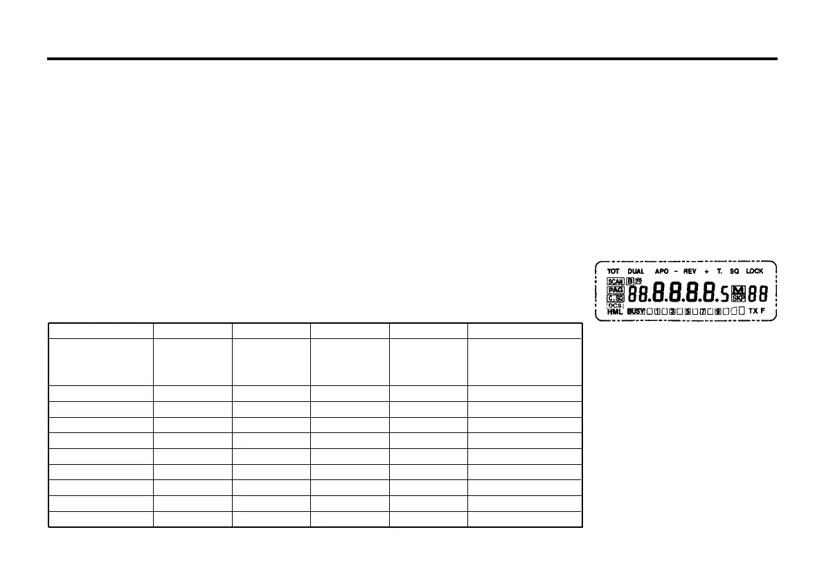
5-4-2 Initial State
Initial state of the transceiver from the factory is shown in the chart
below.
1. RX frequency
2. TX offset frequency
3. TX offset direction
4. Repeater access tone
5. CTCSS tone frequency
6. DCS code/polarity
7. C.SQ code
8. CTCSS/DCS status
9. PAG/C.SQ status
10. Automatic repeater mode status
11. DTMF TX speed
12. DTMF TX delay time
5-4-3 System Memory Initialization
● Memory channel Initialization (System Reset)
When you want to erase all programmed data or if the display
shows erroneous information, you should initialize (reset) the
transceiver using the following procedure.
1. Turn the PWR switch off.
2. Press and hold the MR/M key and turn on the PWR switch.
3. Release the MR/M key.
● VFO Initialization(VFO Reset)
All the settings, except the contents of the memory and call
channel, are initialized.
1. Turn the PWR switch off.
2. Press and Hold the VFO/MV key then turn
the PWR switch on.
3. Release the VFO/MV key .
AR-147 AR-247
VFO/Memory
channel 1/ CALL
144.000 223.500
440.000
channel frequency
MHz
MHz MHz
VFO step 10kHz 10kHz 10kHz
Memory channel
1 CH
1 CH
1 CH
CTCSS frequency
88.5Hz 88.5Hz 88.5Hz
DCS code
263 263 263
DCS Polarity Tx/Rx Normal Tx/Rx Normal Tx/Rx Normal
Repeater Access Tone
1750 Hz 1750 Hz 1750Hz
Offset Frequency
600KHz 1.6MHz 5MHz
DTMF speed
50ms 50ms 50ms
DTMF Tx delay 450 ms 450 ms 450ms
AR-447
144.000
MHz
10kHz
1 CH
88.5Hz
263
Tx/Rx Normal
1750Hz
600KHz
50ms
450ms
TM281A
245.000
MHz
10kHz
1 CH
88.5Hz
263
Tx/Rx Normal
1750Hz
1.6MHz
50ms
450ms
COMMANDO 246BM