PRODUCT OVERVIEW
6
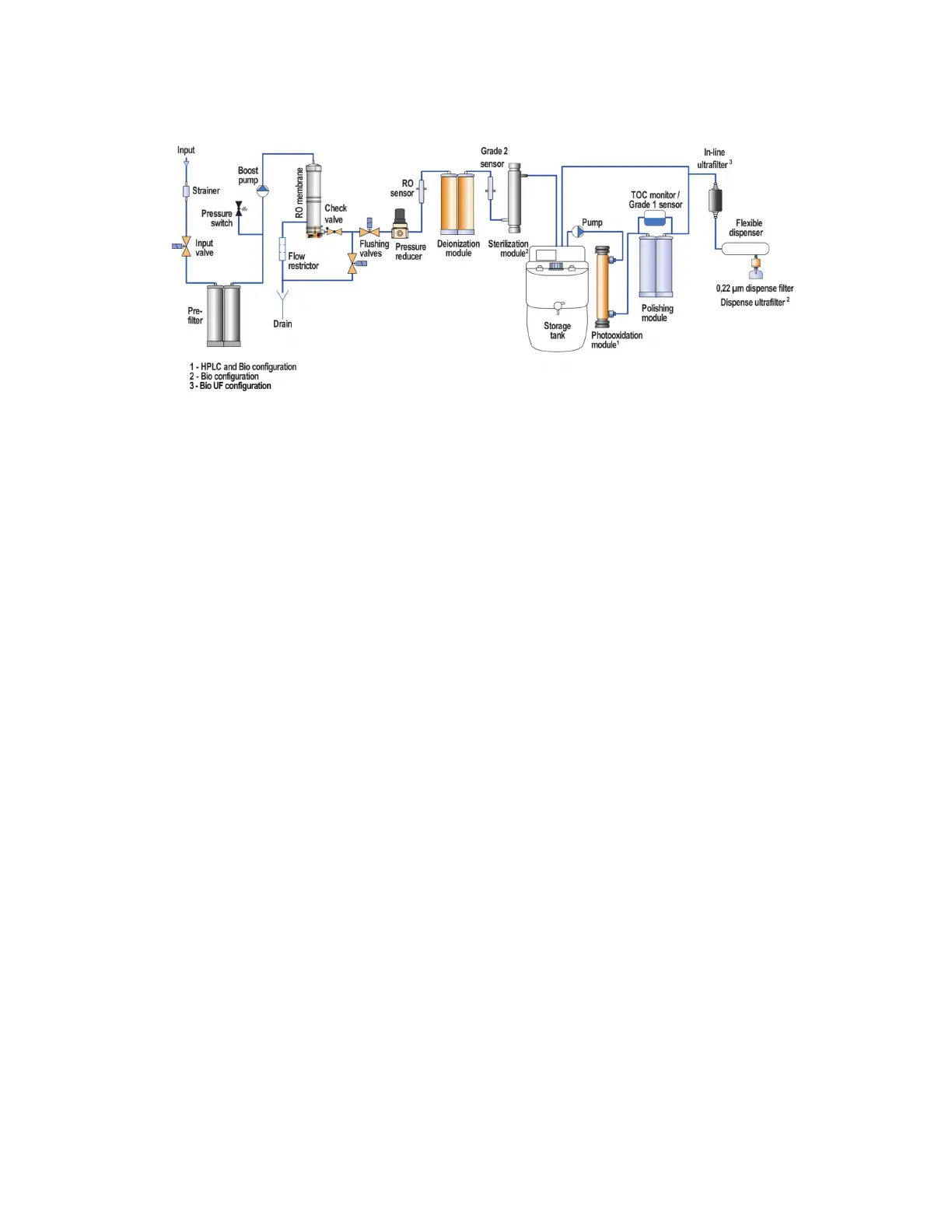
System Components in Flow Chart
Principle
The hydraulic diagram (flowchart) of the Adrona Q-Front N water purification system is shown in
Q-Front N Trace and Q-Front N HPLC/ Bio/ Bio UF flow charts above.
The input valve controls intake of feed water from the tap. The first purification stage consists of the
pre-filter cartridge (part no. 10411) including activated carbon intended to remove particles, free
chlorine, organics and colloids. A pressure switch controls feed water pressure.
The boost pump is used to maintain pressure at the level necessary for the efficient operation of the
reverse osmosis membrane, deionization module (part no. 10311), and UV sterilization module (Bio
configuration only). The feed flow goes to the membrane where it splits into two parts: the permeate,
diffused through the membrane, and the concentrate which passes over the membrane, carrying away
contaminants to drain. The permeate goes to the third purification step – deionization module (part
no. 10311) where the remaining dissolved contaminants are removed.
Before entering the tank, water is sterilized by an UV lamp (Bio configuration only, also available as an
option). Water quality is controlled by Grade II water conductivity sensor. LCD display provides
information about the system status.
Purified water is stored in the tank. Water in the tank meets the requirements of ISO 3696 Grade II.
In order to obtain Grade I water, there is a recirculation loop connected to the tank.
For Trace modification this loop includes recirculation pump, polishing module (part no.
10031), Grade I sensor as well as dispense port with microfilter (part no. 10012).
HPLC, Bio and Bio UF configuration additionally includes photooxidation module (part no.
10018) and TOC monitor.
Q-Front N Bio system has an ultrafilter (part no. 10120) instead of microfilter.
Q-Front N Bio UF system has an in-line ultrafilter (part no. 11200) before microfilter.