6270ADT Installation and Setup Guide
2–4
6270-002-V1
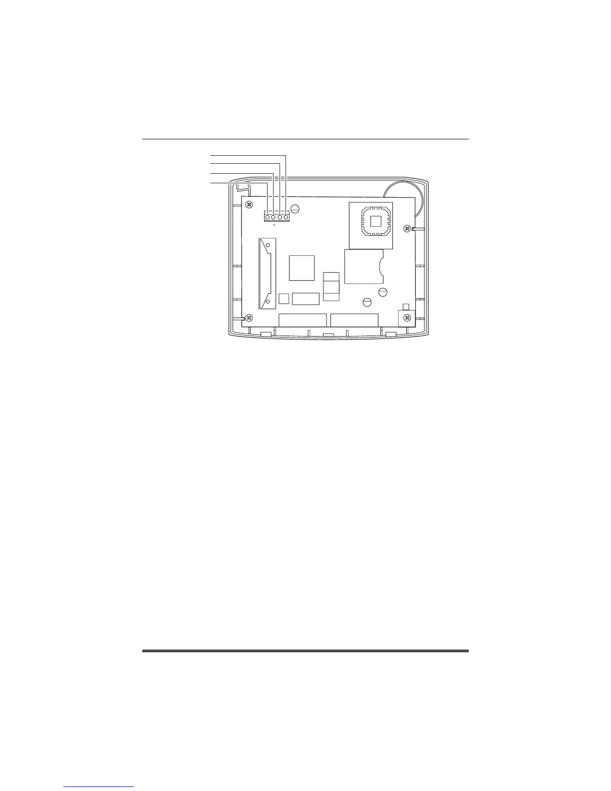
DATA OUT (YELLOW)
GROUND (BLACK)
DATA IN (GREEN)
+12VDC (RED)
G
Y
+
+
+
+
+
Figure 3. Wiring the
6270ADT
3. Connect ground to the 6270ADT using step a or b below.
a. If powering the keypad from the control panel, connect the
AUX – terminal of the control panel to terminal block position
3 (GND terminal of the 6270ADT (black wire)).
b. If powering the keypad from a supplementary power supply,
connect the AUX – terminal of the control panel to the (–)
terminal of the supplementary power supply (black wire).
Then, connect the (–) terminal of the supplementary power
supply to terminal block position 3 (GND terminal of the
6270ADT (black wire)).
4. Connect Data Out terminal of the control panel to terminal block
position 1 (Data In terminal of the 6270ADT (yellow wire)).
5. Connect the Data In terminal of the control panel to header
terminal block position 4 (Data Out terminal of the 6270ADT
(green wire)).
6. Attach the case front of the 6270ADT to the case back. Attach the
top of the case first, and then press the bottom section inward
until it snaps into place securely.
 Loading...