NetVanta 4660/5660 Series Physical Description
617004660F1-34A Copyright © 2014 ADTRAN, Inc. 17
NetVanta 4660/5660 Series Domestic Shipping Contents
Domestic shipments of the NetVanta 4660/5660 Series include the following items:
• NetVanta 4660/5660 base unit
• Set of two 19-inch rack mounting brackets
• Set of 4 rubber mounting feet
• Six mounting screws
• Quick start guide
NetVanta 4660/5660 Series International Shipping Contents
International shipments of the NetVanta 4660/5660 Series include the following items:
• NetVanta 4660/5660 base unit
• Set of two ETSI/23-inch rack mounting brackets
• Set of 4 rubber mounting feet
• Six mounting screws
• Quick start guide
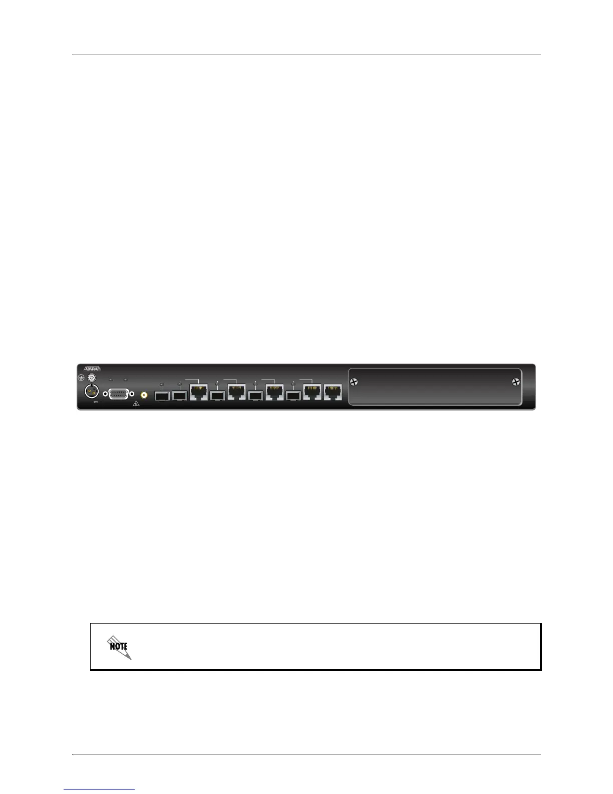
NetVanta 4660/5660 Series Front Panel Design
The NetVanta 4660/5660 Series front panel is shown below along with a description of all connectors and
interfaces.
Figure 1. NetVanta 4660/5660 Series Front Panel Layout
Power Connector
The power connector, labeled 48VDC, provides connection for a 48 VDC power source. Please refer to
Supplying Power to the Unit on page 33 for connection details.
Status LEDs
The STAT LED indicates the unit’s status. The FAN LED reflects the status of the fan. The GIG 0/1
through GIG 0/5 LEDs reflect the status of the 10/100/1000Base-T Ethernet interfaces. See the Table 1
on page 18 for LED behaviors.
CONSOLE Interface
The CONSOLE interface is an EIA-232 serial port (DCE), which provides for local management and
configuration (via a DB-9 female connector). See
Table A-1 on page 35 for the CONSOLE interface
pinouts.
10/100/1000Base-T Ethernet Interfaces
The GIG 0/1 port consists of one SFP slot for connectivity over fiber. The status LED is located above
the interface.
Connection directly to an external modem requires a cross-over cable.
T4
48VDC
GIG 0/1
STAT FAN
GIG 0/2 GIG 0/3 GIG 0/4 GIG 0/5
CONSOLE
NetVanta 4660
1 PPS
OUT
 Loading...