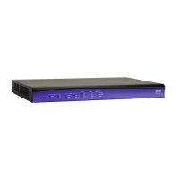
Physical Description NetVanta 4660/5660 Series
18 Copyright © 2014 ADTRAN, Inc. 617004660F1-34A
The GIG 0/2 through GIG 0/5 ports consist of one RJ-45 and one SFP slot for connectivity over fiber.
(Use either the RJ-45 connector or the SFP slot. The fiber slot has precedence.) See Table A-3 on page
36 for the Ethernet interface pinouts. The status LEDs, are located above each interface.
1 PPS 50 ohm Phase Synchronization Measurement Interface
The phase synchronization interface, labeled 1 PPS OUT, provides a one pulse per second output
which can be used to connect to measurement equipment.
• Period: 1 second +/-1 ppm
• Pulse Width: 200 ns (minimum), 500 ms (maximum), 10 us (typical)
• Rise Time: 5 ns (maximum)
• Voh: 5.5 V (maximum), 1.2 V (minimum)
• Vol: 0.3 V (maximum), -0.3 V (minimum)
Timing Interface
The RJ-45 interface, labeled T4, is provided for timing output in both T12 and E12 modes.
Option Slot
The option slot accepts a variety of network modules (refer to Option Modules on page 23).
LED Descriptions
The following table describes LED activity for the NetVanta 4660/5660 Series.
Table 1. Front Panel Status LED Behaviors
LED Color Indication
STAT
Off Unit is not receiving power.
Green (flashing) The unit is powering up. On power up the STAT LED flashes
rapidly for five seconds, during which time the user can escape
to boot mode from the CONSOLE port.
Green (solid) The power is on and self-test passed.
Red (solid) The power is on, but the self-test failed or the application code
could not be booted.
STAT
Off Unit is not receiving power.
FAN
Green (solid) Both fans are functioning properly.
Amber (solid) Only one fan is functioning.
Red (solid) Neither fan is functioning.
GIG 0/1 through
GIG 0/5
Off Port is inactive or administratively disabled.
Green (solid) The link is up.
Amber (flashing) There is activity on the link.
 Loading...