617004660F1-34A Copyright © 2014 ADTRAN, Inc. 35
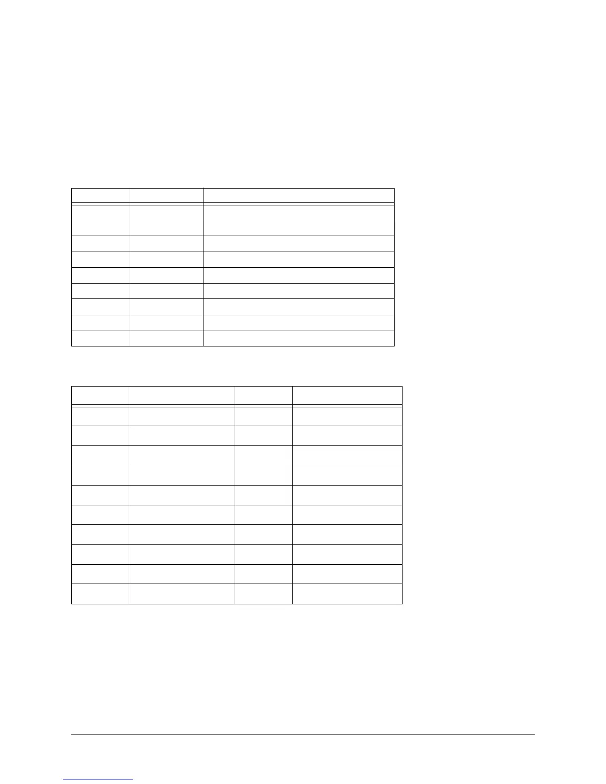
APPENDIX A. CONNECTOR PIN DEFINITIONS
The following tables provide the pin assignments for the base unit and network interface modules (NIMs).
Base Unit Pinouts
Table A-1. CONSOLE Port Pinouts
Pin Name Description
1 DCD Data Carrier Detect (output)
2 RD Receive Data (output)
3 TD Transmit Data (input)
4 DTR Data Terminal Ready (input)
5 SG Signal Ground
6 DSR Data Set Ready (output)
7 RTS Request to Send (input)
8 CTS Clear to Send (output)
9 — Unused
Table A-2. SFP Slot Pinouts
Pin Name Pin Name
1 TGND 11 RGND
2 TX FAULT 12 RX-
3 TX DISABLE 13 RX+
4 MOD DEF(2) 14 RGND
5 MOD DEF(1) 15 VccR
6 MOD DEF(0) 16 VccT
7 RATE SELECT 17 TGND
8LOS18TX+
9RGND19 TX-
10 RGND 20 TGND
 Loading...