www.advancedco.com
20
Note: For additional information regarding the installation and operation of the AV-ZS audio zone splitter
module, refer to AV-ZS Audio Zone Splitter Module Installation Instructions.
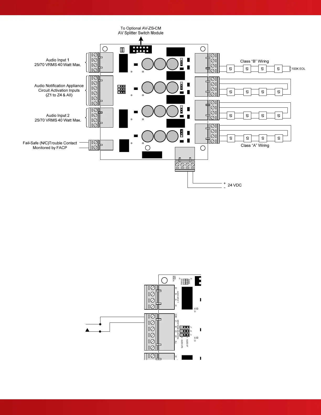
3.2.5.2.1 AV-ZS Speaker Circuit Activation
The AV-ZS audio zone splitter module speaker circuits are activated by switching the common (COM) of the Input
Zone Selection terminal block, through an activation relay contact back to the specific Input Zone Selection (Z1, Z2,
Z3, Z4) terminal block for the specific speaker circuit activation. In addition, the Input Zone Selection terminal block
incorporates an ALL input selection for activating all speaker circuits (see figure 11).
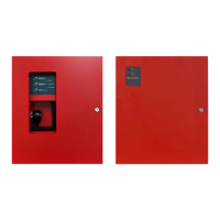
AUDIO INPUT 1
B+ B- A- A+
AUDIO INPUT 2
B+ B- A- A+
INPUT ZONE SELECTION
COM Z1 Z2 Z3 Z4 ALL
TROUBLE
COM N/O
A+ A- B- B+
ZONE 4
A+ A- B- B+
ZONE 3
A+ A- B- B+
ZONE 2
A+ A- B- B+
ZONE 1
+24
V
0
V
+24
V
0
V
O/C Z4
S/C Z4
O/C Z3
S/C Z3
O/C Z2
S/C Z2
O/C Z1
S/C Z1
CLASS
B A
CLASS
B A
CLASS
B A
CLASS
B A
J11 J10 J9 J5
J7 J6 J1
J2
J3
TROUBLE
POWER
LEDS
REMOTE
+24V
DC IN
1 AUDIO I/P
2 AUDIO I/PS
Figure 10 – Optional AV-ZS Audio Zone Splitter Module
Figure 11 – AV-ZS Speaker Circuit Activation
 Loading...