www.advancedco.com
42
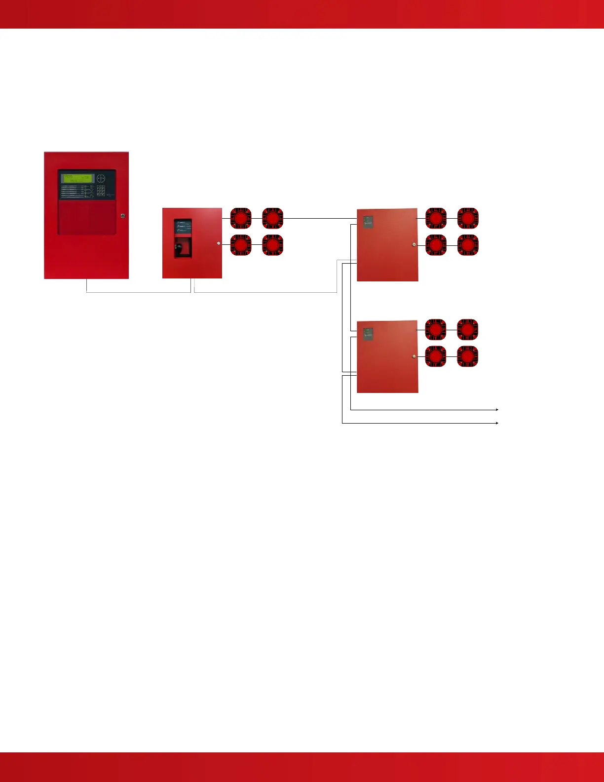
6.3.4 AV-VBM Interfaced to a Listed (Host) Fire Alarm Control Panel and the AV-VB
Distributed Audio Booster (Synchronized Messages/Tones)
AV-VBM Audio Panel w/Microphone Interface to AV-VB Distributed Audio Booster
(Synchronized Audio)
AV-VBM
Audio Panel
Host FACP
40W Speaker Circuit
AV-VB
Distributed Audio Booster
Signaling Line Circuit – Booster Control and Supervision
Microphone Bus
40W Speaker Circuit
Microphone Bus
Signaling Line Circuit – Booster Control and Supervision
40W Speaker Circuit
40W Speaker Circuit
40W Speaker Circuit
40W Speaker Circuit
The host FACP activates the AV-VBM via trigger input #1 or #2 (trigger
#1 message/tone one, trigger #2 message/tone two).
The Microphone Bus connects the audio output of the AV-VBM to the
audio inputs of each AV-VB.
The host FACP activates the AV-VBs via trigger input #3 which
rebroadcasts the AV-VBM Audio/Microphone Riser audio/live voice
(synchronized).
Press All Call switch and key microphone to page all speaker zones.
AV-VB
Distributed Audio Booster
Signal is identical to
Microphone Bus circuit
from AV-VBM
Signal is identical to
Microphone Bus circuit
from AV-VBM
1.
2.
3.
4.
To next
AV-VB
Distributed Audio Booster
 Loading...