www.advancedco.com
www.advancedco.com
21
Note: Speaker circuit activation is unsupervised; wiring must be within 20 feet of the activation relay
contact. When the AV-ZS audio zone splitter module is utilized with a PBUS (RS485) AV-AMP-80 amplifier,
the “All” Input Zone Selection must be constantly activate, allowing tracking of the two (2) onboard AV-
AMP-80 amplifiers for audio control via the AX-CTL base card PBUS (RS485). For additional information
regarding the installation and operation of the AV-ZS audio zone splitter module refer to AV-ZS Audio Zone
Splitter Module Installation Instructions.
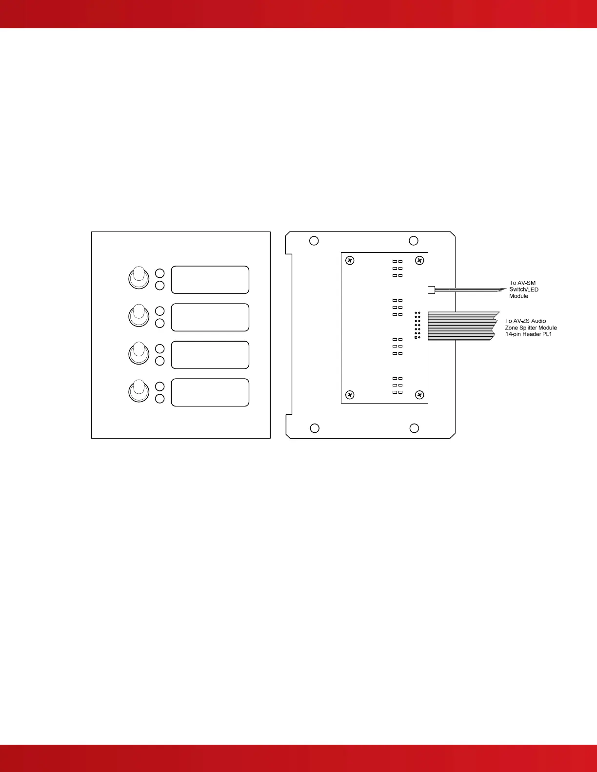
3.2.5.3 Optional AV-ZS-CM AV Splitter Switch Module
The optional AV-ZS-CM AV splitter switch module is a switch module that allows for the individual manual control of
the AV-ZS audio zone splitter module’s four (4) audio notification appliance circuits.
The AV-ZS-CM AV splitter switch module mounts to the available aperture location located on the AV-VBM audio
panel inner door. Two cables are provided with the AV-ZS-CM module, one 2-pin and one 14-pin. The 2-pin cable
connects the AV-ZS-CM module to the AV-VBM AV-SM switch/LED module, while the 14-pin cable connects the
AV-ZS-CM module to the AV-ZS audio zone splitter module (see figure 12).
Note: For additional information requiring the installation and operation of the AV-ZS-CM AV splitter switch
module, refer to AV-ZS Audio Zone Splitter Module Installation Instructions.
Figure 12 – AV-ZS-CM Module
 Loading...