www.advancedco.com
www.advancedco.com
27
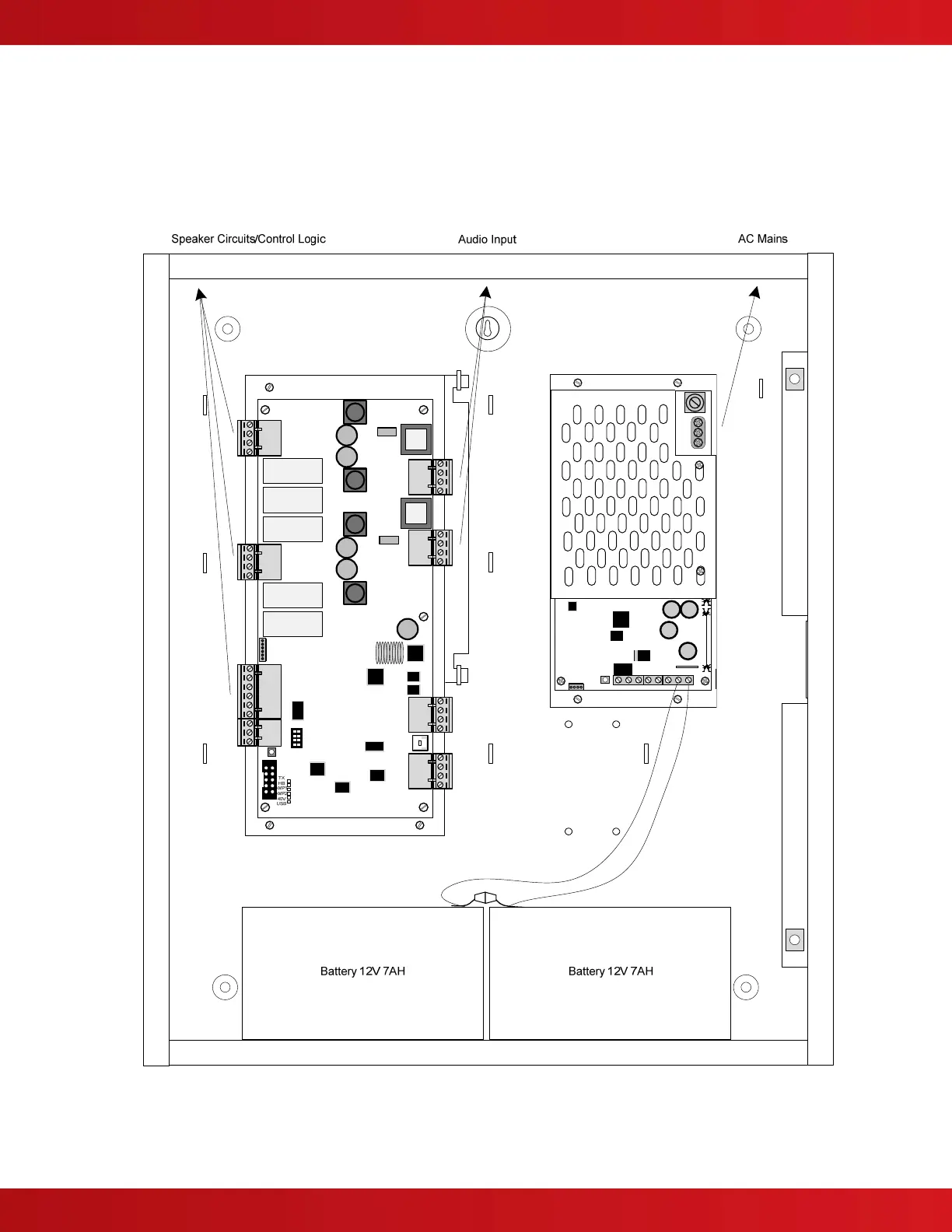
4 Recommended Cable Routing
Power limited and non-power limited circuit wiring must remain separate in the cabinet. All power limited circuit
wiring must remain at least 0.25” (6.35 mm) away from any non-power limited circuit wiring. Furthermore, all power
limited and non-power limited circuit wiring must enter and exit the cabinet through different knockouts and/or
conduits (see figure 18).
Below is a typical diagram for the AV-VBM and AV-VB to meet power limited wiring requirements:
OUT- OUT+
IN- IN+
AMP1
OUT- OUT+
IN- IN+
AMP2
+24V GND +24V
GND
POWER
B A B
A
RS485
AMP-1
A+ A- B-
B+
AMP-2
A+ A- B-
B+
INPUTS
IN1 GND IN2 GND IN3
GND
TROUBLE
COM NO NC
Figure 18 – AV-VBM and AV-VB Cable Routing
 Loading...