www.advancedco.com
22
3.3 AV-SM Switch/LED Module (AV-VBM only)
To allow for control and status of an AV-VBM audio panel w/microphone an AV-SM switch/LED module is provided
behind a locked outer door. The AV-SM switch/LED module is the user interface to the AV-VBM audio panel
w/microphone.
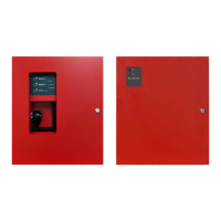
The AV-SM switch/LED module provides three (3) status LEDs and three (3) control switch’s (see figure 13). In
addition to providing the status indicators and control switches, the AV-SM switch/LED module also incorporates
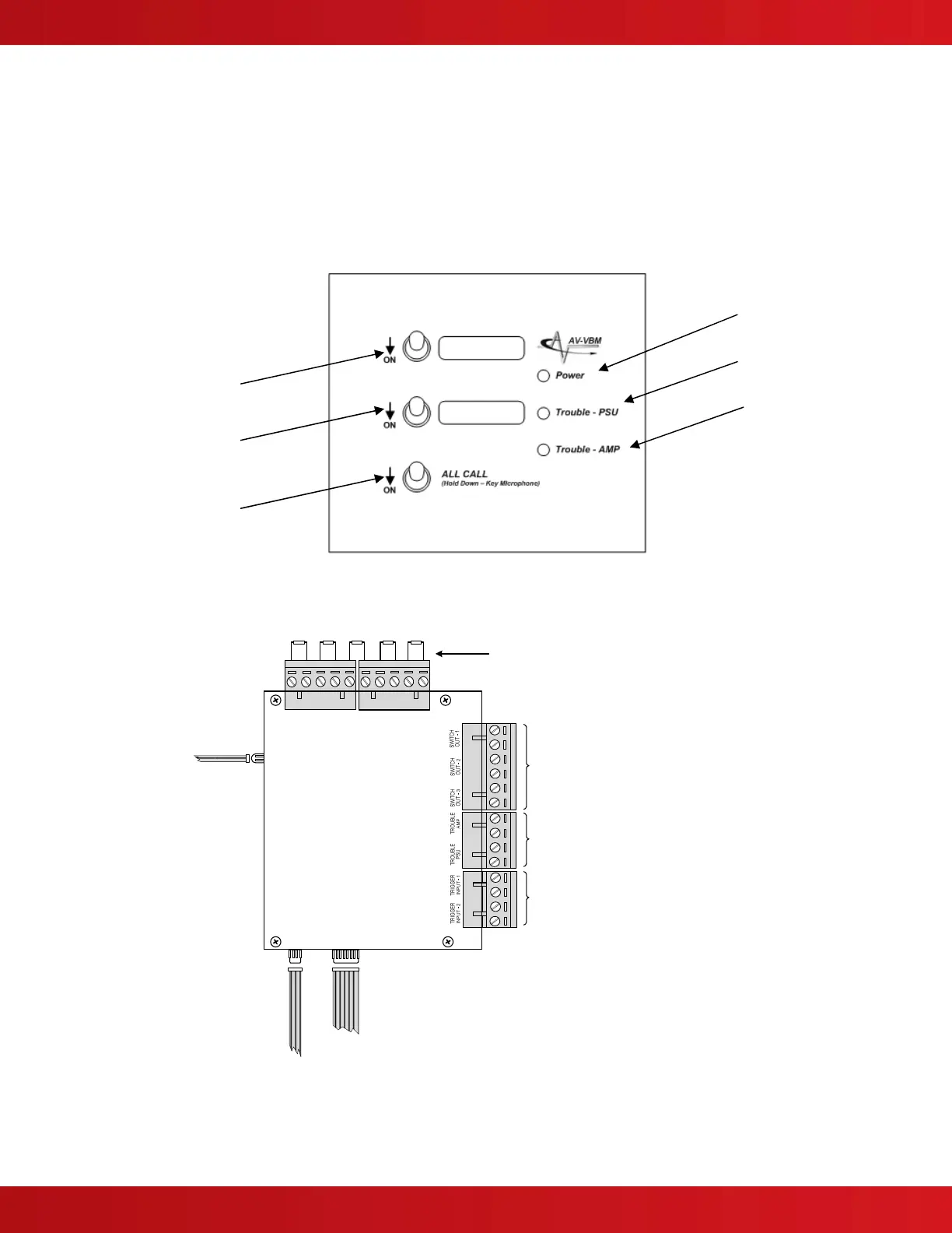
screw terminals for host panel interface for supervision and control of the AV-VBM audio panel w/microphone (see
figure 14).
TYPICAL EOLs
Host FACP EOL Resistors
Use EOL Resistors as required
*Trouble Relays
24V AC/DC, 1.0A PF=1
POWER LIMITED
* FAIL-SAFE, Open Contact Energized when Normal
Trigger Inputs
POWER LIMITED
TRIGGER INPUT-1 – Activate Message 1
TRIGGER INPUT-2 – Activate Message 2
Use normally open contact, activate when closed. Not supervised,
wiring close nippled or within 20 feet in conduit.
Control Switch Status Outputs
Voltage-Free (Open Contact)
POWER LIMITED
SWITCH OUT-1 – Message 1 Switch Activated
SWITCH OUT-2 – Message 2 Switch Activated
SWITCH OUT-3 – All Call Switch Activated
SWITCH
OUT-3
SWITCH
OUT-2
SWITCH
OUT-1
TRBL
PSU
TRBL
AMP
EOL Resistors
To AX-PSU-6 Trouble Contact
To AV-AMP-80 24 VDC Output
To AV-AMP-80 Trouble Contact
and Trigger Inputs 1 thru 3
To Optional AV-ZS-CM
AV Splitter Switch Module
Figure 14 – AV-SM Switch/LED Module Wiring
Power LED
Power Supply
Trouble LED
Figure 13 – AV-SM Switch/LED Module Controls and Status
Manual Activation
Message One
Manual Activation
Message Two
Manual Activation
All Call
Amplifier
Trouble LED
 Loading...