Maximum Series Portable Chiller : Air & Water-Cooled : MG Series Instrument
update 08/02/2021
Page: 24
ADVANTAGE ENGINEERING, INC.
525 East Stop 18 Road Greenwood, Indiana 46142
317-887-0729 Fax: 317-881-1277
Service Department Fax: 317-885-8683
Email: service@AdvantageEngineering.com
motor shaft on the end of the pump and comparing its rotation to the directional
arrow on the motor. If the rotation needs to be changed it should be done at the
main power entry by switching any two power conductors at the terminal block or
customer supplied main power disconnect. Recheck rotation before operating the
units.
4. Models with compressor module wire display Fault until the module has timed
out.
5. Caution must be taken when checking rotation to avoid electrical shock.
5. A scroll compressor may make a loud rattling noise when rotating in the wrong
direction.
6. Operating the scroll compressor in the wrong direction will cause the unit to
triponit’sinternaltemperaturelimitandmaycauseunitdamage.Whenthe
temperature limit trips, the compressor must be allowed to cool before it will
restart. Thermal overload cooling and reset may take substantial time.
7. Procedure to set proper rotation:
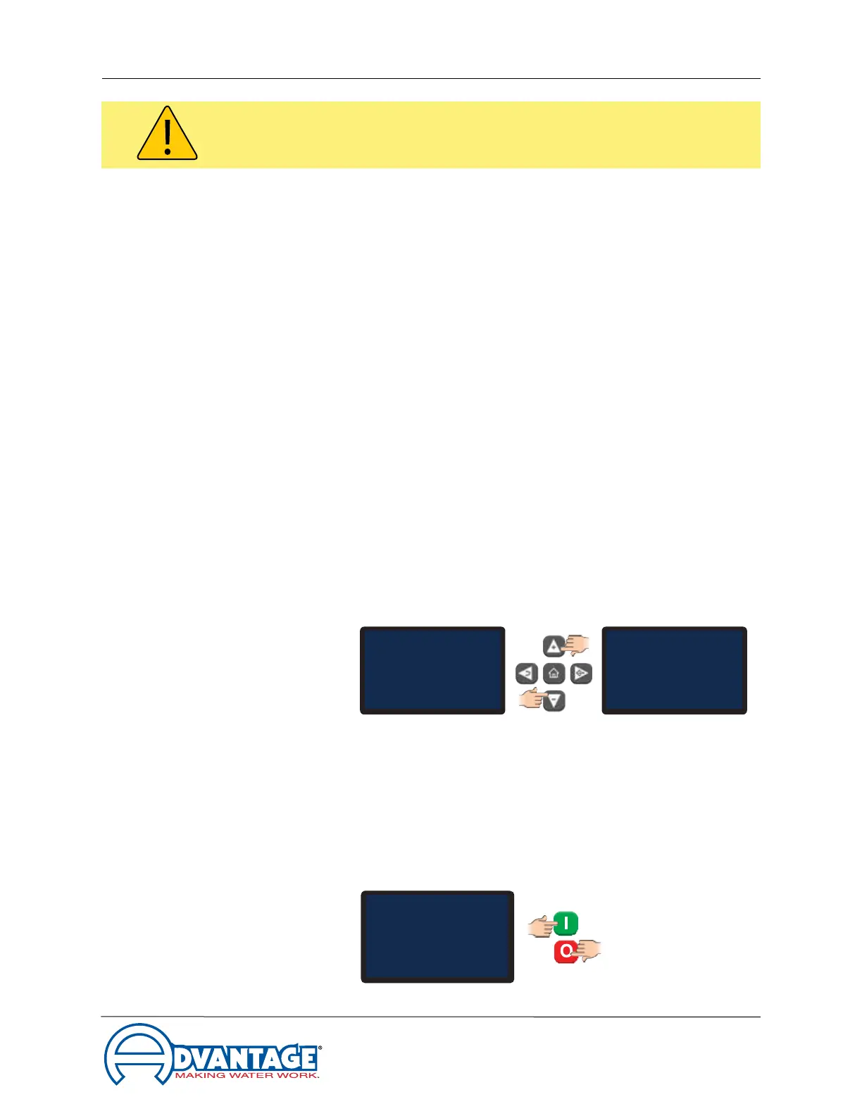
a. Supply electrical power to the unit. Once the correct voltage is supplied
to the unit, the control instrument will read "Standby" or "Status Ready".
Adjust the setpoint to 70°F or higher to prevent the compressor from
activating during this procedure. See Section 3.5 for additional details.
b. Remove all necessary cover panels to access the pump motor.
c. Locatethepump’selectricmotor.Theoperatormustidentifythemotor
shaft inside the electric motor housing. The motor shaft can be seen
through the vent slots in the motor housing or by removing the shaft
cover.
d. Depress the Green "I" start button then the Red "O" stop buttons. This
will quickly cycle the pump motor.
To Process
Setpoint
: 50°F
Circulating
50°F
SetpointStatus
Ready
50°F
Standby
SetpointStatus
Ready
50°F
Standby
SetpointStatus
Ready
70°F
Standby
WARNING: The electrical power is engaged at this point. Caution must be observed while the
electrical supply is engaged and cabinet panels are removed and opened.