update 08/02/2021
Maximum Series Portable Chiller : Air & Water-Cooled : MG Series Instrument
Page: 59
ADVANTAGE ENGINEERING, INC.
525 East Stop 18 Road Greenwood, Indiana 46142
317-887-0729 Fax: 317-881-1277
Service Department Fax: 317-885-8683
Email: service@AdvantageEngineering.com
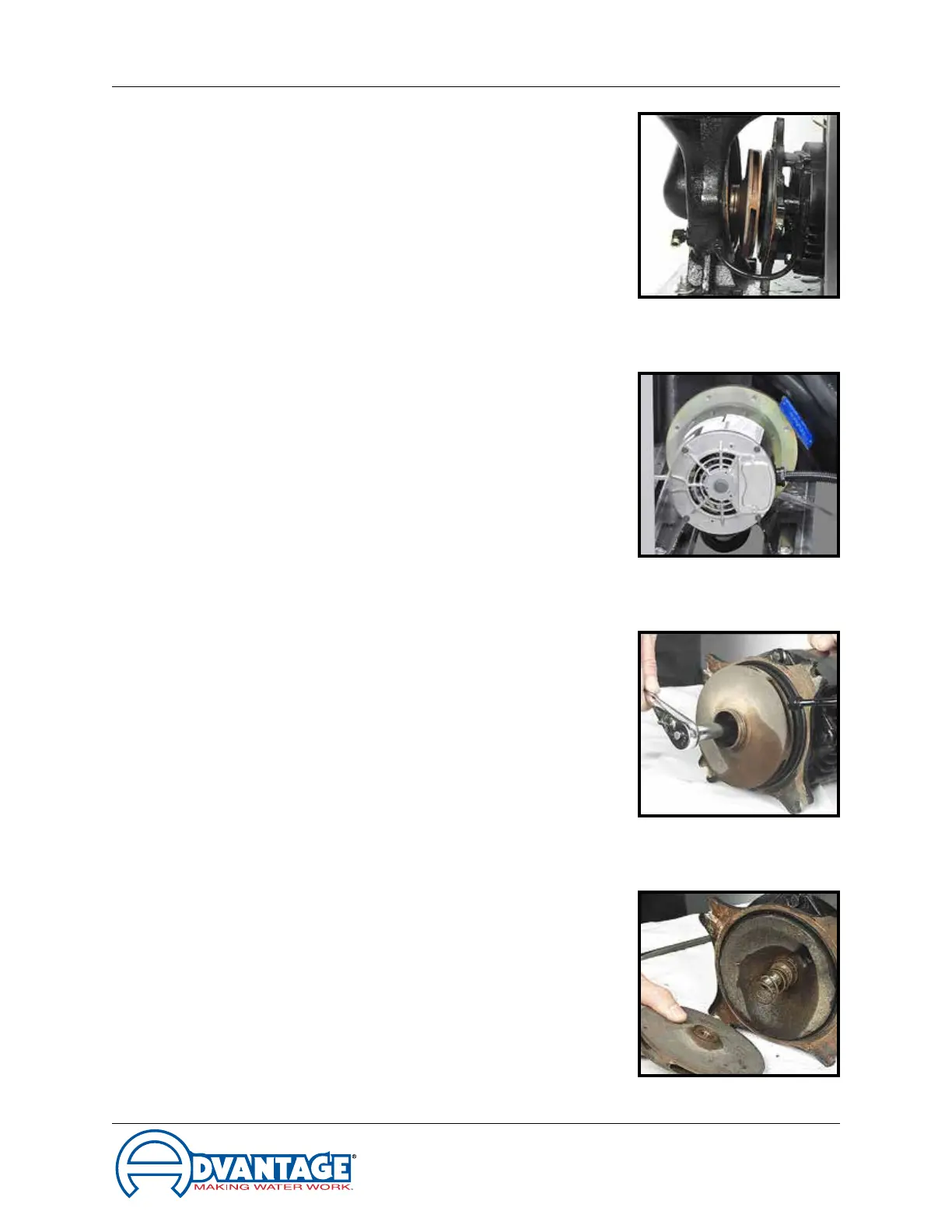
Motor shaft
Figure 5.5F
Typical impeller Figure 5.5G
Impeller Figure 5.5E
Seal components Figure 5.5H
adapter from the unit and place on a workbench
to continue the procedure.
8. Locate and remove the dust cap from motor
end to expose slotted motor shaft. The motor
shaft is free to rotate, but must be secured to
remove the impeller. To secure the motor shaft,
insertaatbladedscrewdriverinslottohold
the shaft stationary (Figure 5.5F).
9. Locate and remove impeller locking screw
(Figure 5.5G). Using a socket and ratchet, the
impeller retaining screw can be removed. Once
the retaining screw is removed, the impeller can
be “unthreaded” from the motor shaft to expose
the pump seal assembly.
10. Remove all seal parts (Figure 5.5H). Note
seal component arrangement to facilitate
reassembly.
11. Clean motor shaft and lubricate with a mild
soap solution.
12. Install new stationary seal member in pump
casingcavity(gure5.5I).Theoperatormust
be certain the stationary seal member is fully
squared and seated in cavity.
13. Slide the rotating member onto lubricated pump
shaft(gure5.5J).Theoperatormustbecertain
not to damage or tear rubber bellows assembly.
14. Place the spring onto the rotating member.
15. Align the impeller, spring and rotating member
beforereinstallingtheimpeller(gure5.5K).
The operator must be certain the spring and
rotating member are aligned before the impeller
is fully tightened and the impeller retaining
screw is reinstalled.
16. Clean pump casing, cavities, impeller and
O-ring before reassembly.
17. Mate the motor and motor adapter to the pump
casing. Reinstall the pump casing bolts.
18. Reconnect the motor power cord and leads.
19. Restore all cover panels as were removed.