EasyManua.ls Logo

Advantech Adam-4016 User Manual

Advantech Adam-4016
398 pages
To Next Page IconTo Next Page
To Previous Page IconTo Previous Page
Page #189 background imageLoading...
Page #189 background image
Chapter 4 Command Set 4-105
Chapter 4
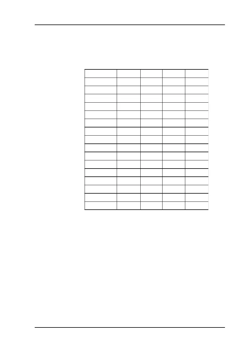
Status Code DO0 DO1 DO2 DO3
OO OFF OFF OFF OFF
O1 OFF OFF OFF ON
O2 OFF OFF ON OFF
O3 OFF OFF ON ON
O4 OFF ON OFF OFF
O5 OFF ON OFF ON
O6 OFFONONOFF
O7 OFF ON ON ON
O8 ON OFF OFF OFF
O9 ON OFF OFF ON
OA ON OFF ON OFF
OB ON OFF ON ON
OC ON ON OFF OFF
OD ON ON OFF ON
OE ON ON ON OFF
OF ON ON ON ON
@AADI
OO (for ADAM-4016) is a hexdecimal number representing the
status of the four digital output channels. The corresponsing
table is show in the following table:
II is a hexadecimal number representing the Digital input ports
channel status(00h = D/I channel is Low, 01h = channel is
High).
(cr)
represents terminating character,
carriage return (0Dh).
Example command: @15DI(cr)
response: !510001(cr)
The analog input module at address 15h is instructed to return
digital I/O data and alarm status.
The module responds that both digital output channels are
OFF, digital input is HIGH, and alarm state is Momentary.
4011, 4011D, 4012, 4014D, 4016

Table of Contents

Question and Answer IconNeed help?

Do you have a question about the Advantech Adam-4016 and is the answer not in the manual?

Advantech Adam-4016 Specifications

General IconGeneral
Input Channels16
Analog InputYes
Resolution16-bit
CommunicationRS-485
ProtocolModbus RTU
Isolation Voltage3000 VDC
Input TypemV, V, mA
Input Range0 to 20 mA, 4 to 20 mA
Accuracy±0.1% of FSR
Sampling Rate10 samples/second (total)
Power Supply10 to 30 VDC
Operating Temperature-10°C ~ +60°C (14°F ~ 140°F)
Storage Temperature-25 ~ 85 °C (-13 ~ 185 °F)
Humidity10 ~ 95% RH (non-condensing)
Weight300 g

Summary

Chapter 1 Introduction

1.1 Overview

Provides a general description of the ADAM Series modules, their features, and power requirements.

Chapter 2 Installation Guideline

2.2 Basic configuration and hook-up

Explains the default factory settings and the basic procedure for configuring and connecting ADAM modules.

2.3 Baud rate and Checksum

Covers the process of setting the baud rate and enabling/disabling the checksum feature for reliable communication.

Chapter 3 I/O Modules

3.1 ADAM-4011/4011D/4012/4013/4015 Analog Input Modules

Describes the functionality and specifications of various ADAM analog input modules, including thermocouple and RTD types.

3.3 ADAM-4017/4017+/4018/4018M/4018+ 8-channel Analog Input Modules

Covers 8-channel analog input modules, including differential and thermocouple types, and data logger functionality.

3.6 ADAM-4050/4051/4052/4053/4055 Digital I/O Modules

Describes various ADAM digital I/O modules, including isolated and non-isolated types, and their channel configurations.

3.8 ADAM-4080/4080D Counter/Frequency Input Modules

Covers counter and frequency input modules, including programmable digital filters and thresholds for signal processing.

Chapter 4 Command Set

4.3 I/O Module Commands Search Table

Provides a comprehensive table listing commands for different I/O modules, including their syntax and function.

4.4 Analog Input Module Command

Details the command set specific to analog input modules, covering configuration, data reading, and calibration.

4.5 Analog Output Module Command

Outlines the commands for configuring and controlling ADAM analog output modules, including calibration and data output.

4.6 Digital I/O and Relay Output Module Command

Lists commands for controlling digital I/O and relay output modules, covering data input/output and status checks.

4.7 Counter/Frequency Module Command

Details commands for counter and frequency modules, including configuration, setup, and data retrieval.

Chapter 5 Calibration

5.1 Analog Input Module Calibration

Explains the software-based calibration procedures for ADAM analog input modules, including zero and span calibration.

5.3 Analog Output Calibration

Describes the process for calibrating ADAM analog output modules, focusing on setting output values for current and voltage ranges.

Appendix B Data Formats and I/O Ranges

B.1 Analog Input Formats

Explains the different data formats for analog input modules, including Engineering Units, Percent of FSR, and Twos Complement Hexadecimal.

Related product manuals