Calibration
5-2 ADAM 4000 Series User's Manual
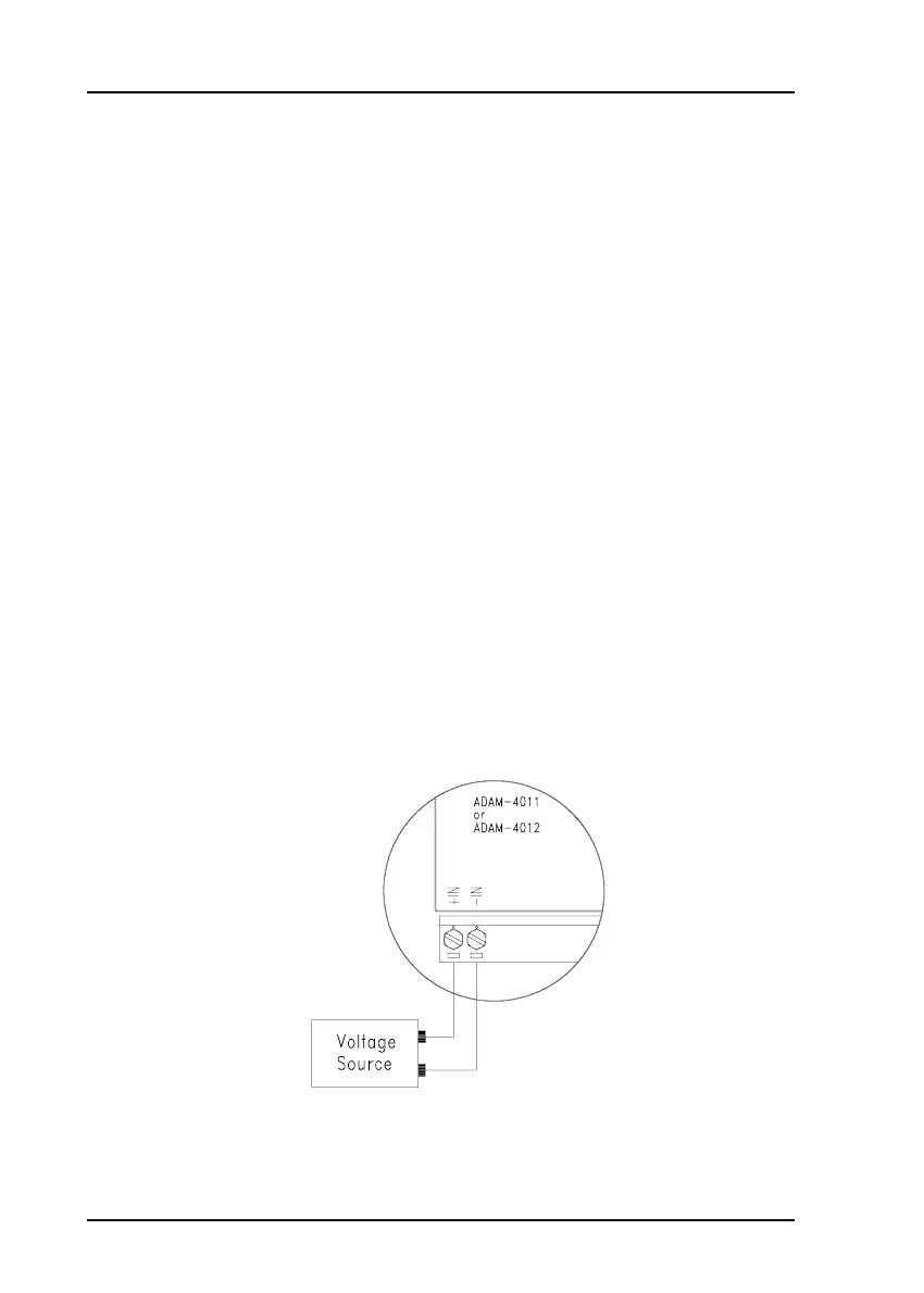
Figure 5-1
Applying Calibration Voltage
Analog input/output modules are calibrated when you receive them.
However, calibration is sometimes required. No screwdriver is necessary
because calibration is done in software, with calibration parameters stored
in the ADAM module’s onboard EEPROM.
The ADAM modules come with utility software that supports the calibra-
tion of analog input and analog output. Besides the calibration that is
carried out through software, the modules incorporate automatic Zero
Calibration and automatic Span Calibration at bootup or reset.
5.1 Analog Input Module Calibration
Models: ADAM 4011, 4011D, 4012, 4014D, 4016, 4017, 4017+, 4018, 4018+,
4018M
1. Apply power to the module and let it warm up for a bout 30 minutes
2. Assure that the module is correctly installed and is properly configured
for the input range you want to calibrate. You can do this by using the
ADAM utility software. (Refer to Appendix D, Utility Software.)
3. Use a precession voltage source to apply a calibration voltage to the
module’s +IN and -IN terminals of the ADAM-4011, 4011D and 4012.
Use a precession voltage source to apply a calibration voltage to the
module’s Vin+ and Vin- terminals (or Iin+ and Iin-) for the ADAM-4014D
and 4016. Use a precession voltage source to apply a calibration voltage
to the module’s Vin0+ and Vin0- terminals for ADAM-4017, 4017+, 4018,
4018+ and 4018M.