Chapter 5
Chapter 5 Calibration 5-7
Use a precision resistance decade box or discrete resistors with values:
10 W, 15 W, 60 W, 140 W, 200 W and 440 W.
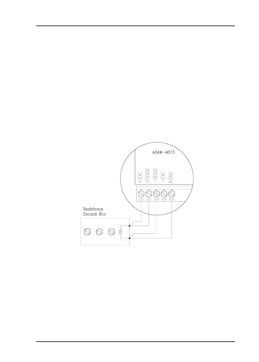
4. Apply the reference Offset resistance to the terminals of the module.
(Refer to Figure 5-5 for the correct wiring diagram and to Table 5-2 to
choose the right Offset calibration resistance.)
Figure 5-5
Applying calibration resistance
5.2 Analog Input Resistance Calibration
Model: ADAM-4013
1. Apply power to the module and let it warm up for about 30 minutes.
2. Assure that the module is correctly installed and is properly config-
ured for the input range you want to calibrate. You can do this by
using the ADAM utility software. (Refer to Appendix D, Utility
Software.)
3. Apply the reference Span resistance to the terminals of the screw
terminals using a 4-wire connection. Refer to Figure 5-5 for the
correct wiring diagram and to Table 5-2 to choose the right Span
calibration resistance).