2-8 ADAM-5510/P31
Installation Guideline
2.5 Jumper Settings and DIP Switch Settings
This section tells you how to set the jumpers and DIP switches to
configure your ADAM-5510/P31 system. It gives the system default
configuration and your options for each jumper and dip switch. There
are three jumpers (JP2~JP4) on the CPU card, and one 8-pin DIP switch
on backplane board. Note that JP1 is actually a connector.
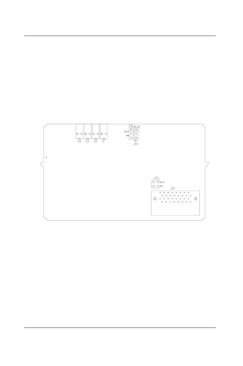
The following figure shows the location of the jumpers:
* JP4 is for battery power ON/OFF
Figure 2-7: Jumper locations on the CPU card
COM2 port RS-485 control mode setting
The COM2 port is dedicated as an RS-485 interface. In an RS-485
network, handshaking signals such as RTS (Request to Send),
normally control the direction of the data flow. A special I/O circuit in
the ADAM-5510/P31 senses the data flow direction and automatically
switches the transmission direction, making handshaking signals
unnecessary. Jumper JP3 gives users the option of configuring the
COM2 port for automatic control or RTS control. Jumper settings are
shown in Figure 2-8:
 Loading...