ADAM-5510/P31 2-9
Chapter 2
Watchdog timer setting
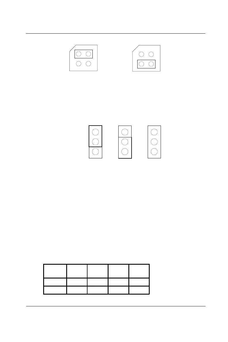
Jumper JP2 on the CPU card lets you configure the watchdog timer to
disable mode, reset mode or NMI (Non-maskable interrupt) mode.
Jumper settings are shown below:
Figure 2-9: Watchdog timer setting
Network address/baudrate setting
Set the network address/baudrate using the 8-pin DIP switch located
on the lower right-hand face of the ADAM-5510/P31 front cover. Valid
address settings range from 0 to 63 (00h to 3Fh) where ON in any of
the 6 DIP switch positions bits 1 through 6 equates to a binary 1, and
OFF equates to a binary 0. For example, if the Node ID is 03h, the DIP
switch settings for switches 1 and 2 (representing bits 1 and 2) would
both be ON while the switches 3, 4, 5, and 6 would be OFF. The
default Node ID is 01h.
The two DIP switch positions bit 7 and bit 8 are for baudrate setting,
as shown in the following table:
JP2
Reset Mode
Disable WDT
JP2
NMI Mode
(Default)
Figure 2-8: COM2 port RS-485 control mode setting (JP3)
JP3 JP3
AUTO
RTS
AUTO
RTS
Automatic Control
(Default)
RTS Control
Table 2-1: DIP switch baudrate settings
Baudrate
(bps)
9600 19200 38400 115200
Bit 7 OFF ON OFF ON
Bit 8 OFF OFF ON ON
 Loading...