AIMB-279 User Manual 12
2.1 Introduction
You can access most of the connectors from the top of the board as it is being
installed in the chassis. If you have a number of cards installed or have a packed
chassis, you may need to partially remove a card to make all the connections.
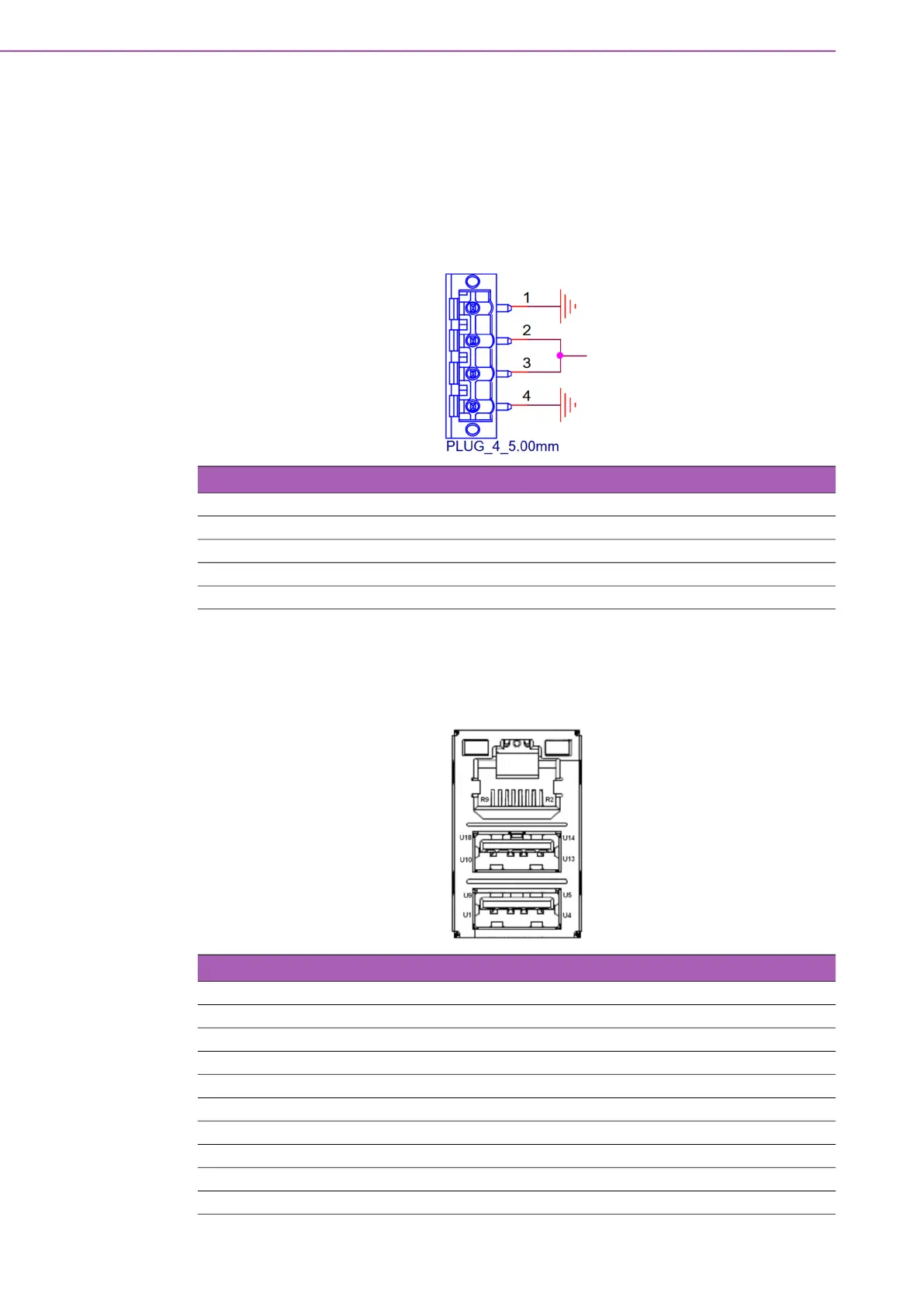
2.2 DC-In Power Connector (DCIN1)
2.3 RJ-45 + USB 3.2 Stack Connector
(LAN1_USB12)
Table 2.1: DC-In Power Connector (DCIN1)
Pin Signal
1 GND
2 ADAPTER VOLTAGE
3 ADAPTER VOLTAGE
4 GND
Table 2.2: RJ-45 + USB 3.2 Stack Connector (LAN1_USB12)
Pin Signal Pin Signal
U1 VBUS U10 VBUS
U2 D_1- U11 D_2-
U3 D_1+ U12 D_2+
U4 GND U13 GND
U5 RX_1- U14 RX_2-
U6 RX_1+ U15 RX_2+
U7 GND U16 GND
U8 TX_1- U17 TX_2-
U9 TX_1+ U18 TX_2+