MIO-5250 User Manual 8
This chapter explains the setup procedures of the MIO-5250 A1 hardware, including
instructions on setting jumpers and connecting peripherals, switches, indicators and
mechanical drawings. Be sure to read all safety precautions before you begin the
installation procedure.
2.1 Jumpers
2.1.1 Jumper List
2.1.2 Jumper Settings
Table 2.1: Jumpers
Label Function
J1 24-bit LVDS1 Power
J2 48-bit LVDS2 Power
J3 Auto Power on setting
J4 COM2 Setting
J5 COM3 setting
J6 Clear CMOS
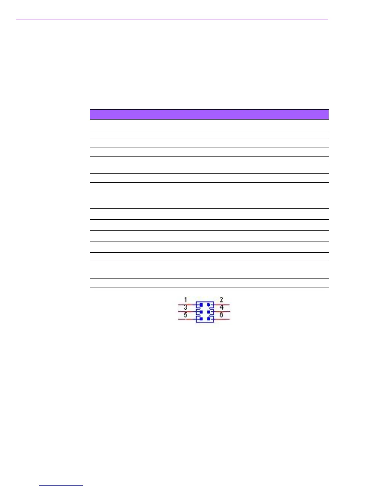
J1 24 bits LVDS1 Power
Part Number 1653003260
Footprint HD_3x2P_79
Description PIN HEADER 3x2P 2.0mm 180D(M) SMD 21N22050
Setting Function
(1-3)* +3.3V
(3-5) +5V
(3-4) +12V