PCIE-1816_1816H User Manual 26
AO Sample Clock Sources Connections
Internal AO Output Clock
The internal AO output clock applies a 100MHz time base divided by a 32-bit counter.
Conversions start on the rising edges of counter output. Through software, user can
specify the clock source and clock frequency to pace the analog output operation.
The maximum frequency is 3.030303MS/s.
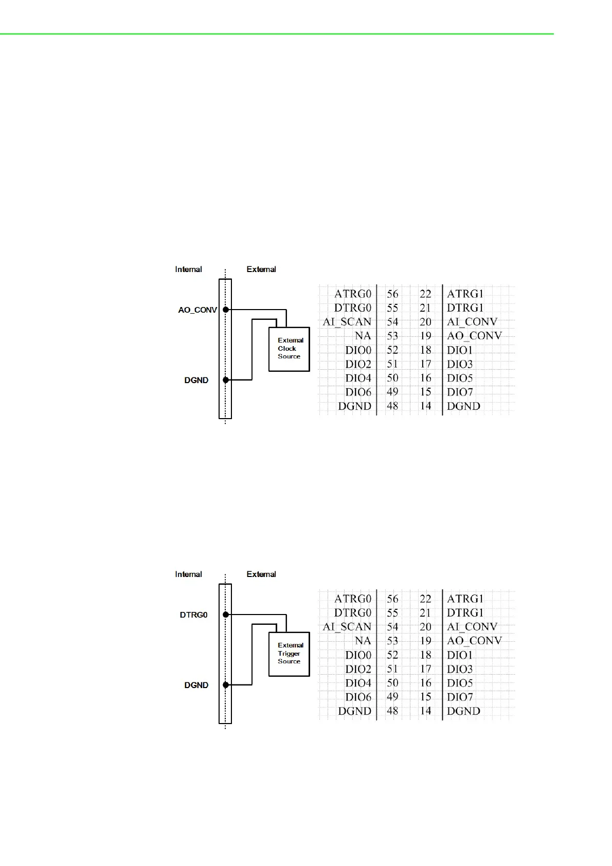
External AO Output Clock
The external AO output clock is useful when you want to pace analog output opera-
tions at rates not available with the internal AO output clock, or when you want to
pace at uneven intervals. Connect an external AO output clock to the pin and then
the conversions will start on input signal's rising edge. You can use software to spec-
ify the clock source as external. The maximum input clock frequency is 3MS/s.
Figure 3.10 External Clock Source Connection
Trigger Sources Connections
External Digital (TTL) Trigger
The PCIE-1816/ 1816H supports External digital (TTL) trigger to activate AO conver-
sions for continuous output mode. An external digital trigger event occurs when the
PCIE-1816/ 1816H detects either a rising or falling edge on the External AO TTL trig-
ger input signal from the pin of connector. User can define the type of trigger source
as rising-edge or falling-edge by software. The trigger signal is TTL-compatible.
Figure 3.11 External Digital Trigger Source Connection