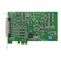
1 PCIE-1816_1816H User Manual
Contents
Chapter 1 Introduction..........................................1
1.1 Features .................................................................................................... 2
1.2 Applications............................................................................................... 3
1.3 Installation Guide ...................................................................................... 3
Figure 1.1 Installation Flow Chart ................................................ 4
1.4 Software Overview .................................................................................... 5
1.5 DAQNavi Device Driver Programming Roadmap ..................................... 5
1.6 Accessories............................................................................................... 6
Chapter 2 Installation............................................7
2.1 Unpacking ................................................................................................. 8
2.2 Driver Installation ...................................................................................... 9
Figure 2.1 Setup Screen of Advantech Automation Software ..... 9
Figure 2.2 Different Options for Driver Setup ............................ 10
2.3 Hardware Installation ............................................................................. 10
2.4 Device Setup & Configuration ................................................................. 11
Figure 2.3 The Device Setting of PCIE-1816/1816H .................11
Figure 2.4 The Device Setting page .......................................... 12
Figure 2.5 The Device Testing of PCIE-1816/1816H ................ 12
Chapter 3 Signal Connections ...........................13
3.1 Overview ................................................................................................. 14
3.2 Switch and Jumper Settings.................................................................... 14
Figure 3.1 Connector and Switch Locations .............................. 14
3.2.1 Board ID (SW1)........................................................................... 15
Table 3.1: Board ID Setting (SW1) ............................................ 15
3.2.2 Power On Configuration(JP1) ..................................................... 15
Table 3.2: Power on Configuration after Hot Reset (JP1) ......... 15
3.2.3 Jumper Settings to Set Ports as Software-configurable or Output
ports ............................................................................................ 16
Table 3.3: Function Description................................................. 16
3.3 Signal Connections ................................................................................. 17
Figure 3.2 68-pin I/O Connector Pin Assignments .................... 17
3.3.1 I/O Connector Signal Description................................................ 18
Table 3.4: I/O Connector Signal Descriptions ........................... 18
3.3.2 Analog Input Connections........................................................... 19
Figure 3.3 Single-ended input channel connections.................. 19
Figure 3.4 Differential input channel connections...................... 20
Figure 3.5 Differential input channel connection - floating signal
source....................................................................... 21
Figure 3.6 External Clock Source Connection........................... 23
Figure 3.7 External Digital Trigger Source Connection ............. 23
Figure 3.8 External Analog Trigger Source Connection ............ 24
Figure 3.9 Analog Output Connections...................................... 25
Figure 3.10External Clock Source Connection........................... 26
Figure 3.11External Digital Trigger Source Connection ............. 26
Figure 3.12External Analog Trigger Source Connection ............27
3.3.3 Digital Signal Connections .......................................................... 27
Figure 3.13Wet and Dry contacts ............................................... 27
Figure 3.14Wet signal connection of digital input ....................... 28
Figure 3.15Dry signal connection of digital input ........................ 28