53 PCIE-1816_1816H User Manual
Appendix B Operation Theory
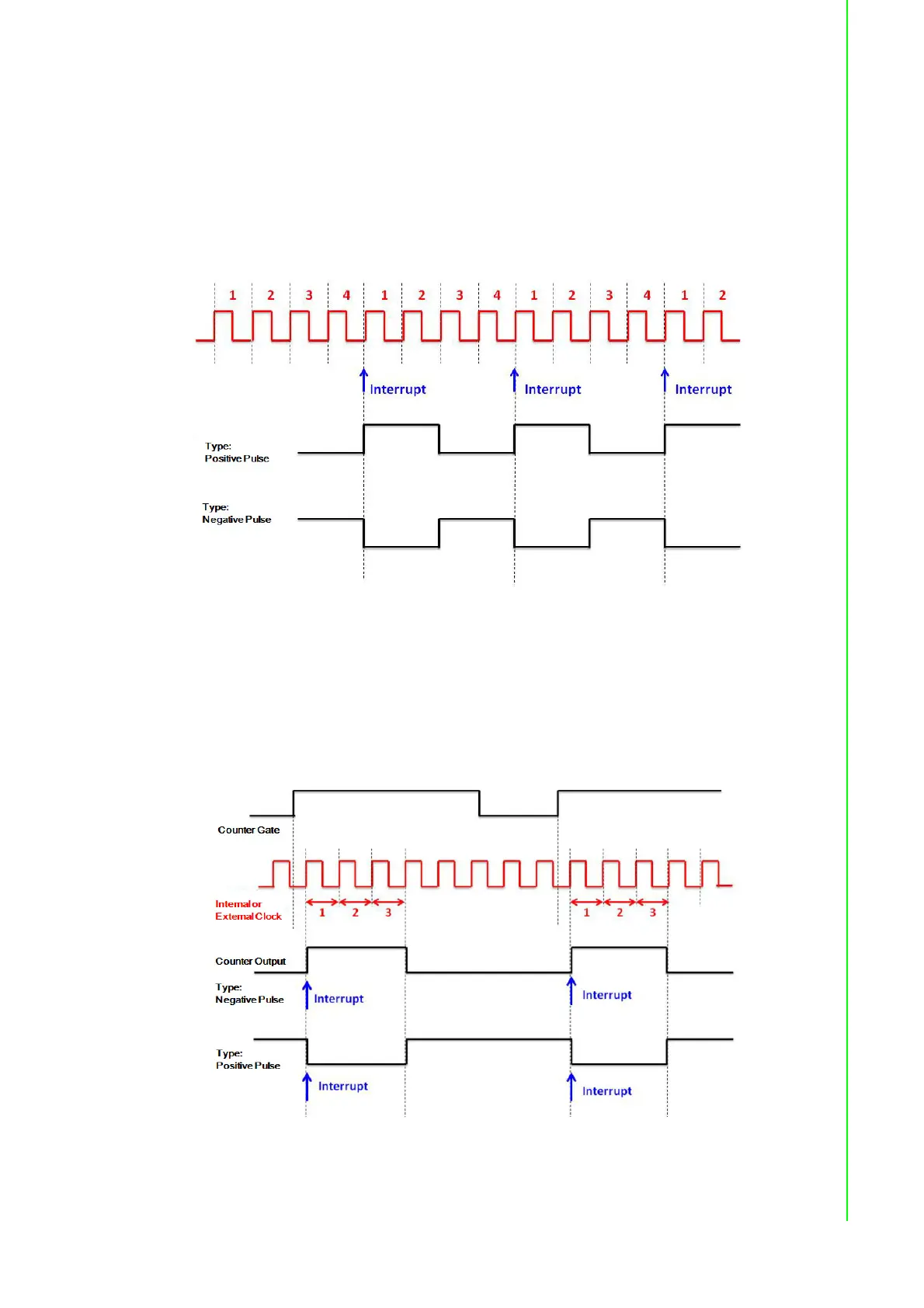
4. Pulse Output with Timer Interrupt
PCIE-1816/1816H counter has internal clock that you can produce periodic out-
put signal with interrupt generated at the same time. PCIE-1816/1816H counter
will use internal clock as time base, to fulfill the frequency you want to set. See
the figure below as example, the desired frequency is 5 MHz. The internal clock
is 20 MHz, so PCIE-1816/1816H will periodically generate output signal and
interrupt every 4 pulses of the internal clock. (20 MHz / 5 MHz = 4). Available
output frequency range is 0.005 Hz ~ 5 MHz.
5. Delay Pulse Generation
Using PCIE-1816/1816H internal clock, you can change the logic level within a
specific period, starting from a trigger signal connecting to counter gate input.
For example, if you define the count equals to 3 (as figure below), a counter out-
put will change its status after 3 pulses of internal clock signals pass, after a trig-
ger signal from counter gate becomes high.