1-2. Caution
1. With POWER ON, self-check is automatically initiated; any failure will pro
duce an error message “E01, E07, E10” for about 2s. When POWER is ON
after RESET ON, check of panel switches is performed (See instruction
manual 3-3-3 for details).
2. When a panel switch is pressed, function is selected and the instrument is in
the standby state; when released, operation is strarted in the TOT. mode,
totalize operation continues but display is held while the ON/OFF switch is
being pressed (GATE lamp on); when released (GATE lamp off), totalized
result is displayed.
3. Though selectable by function selector switch, 4 ^ position on
TR5821/5822 is not used. Move to any other position.
4. In case of frequency measurements (FREQ.B/TR5821, TR5822,
TR5823, TR5823H), when the rapid switching of input frequency
happen, the timing of switched frequency may cause, the
measurement time to get longer.
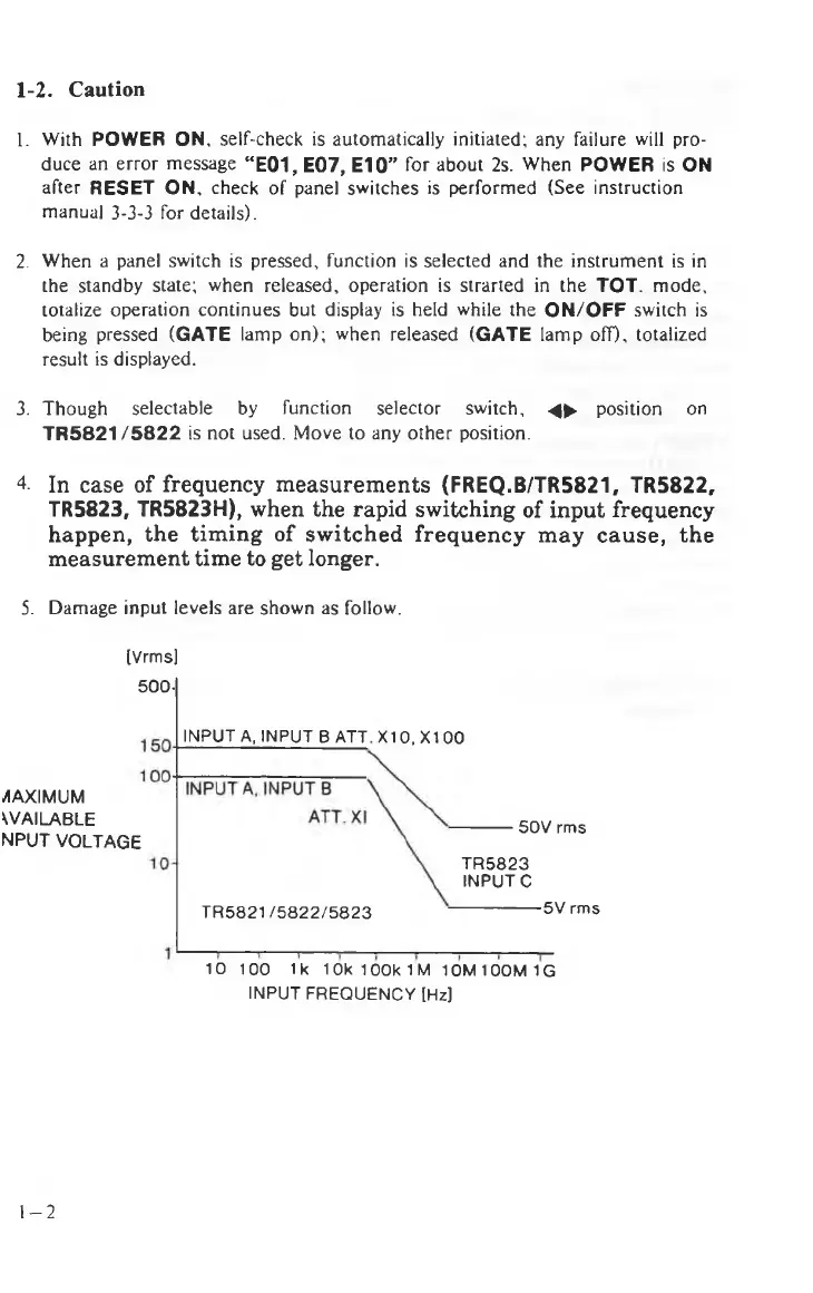
5. Damage input levels are shown as follow.
[Vrms]
500-
INPUT A, INPUT B ATTX10.X1 00
MAXIMUM
AVAILABLE
NPUT VOLTAGE
50V rms
TR5823
INPUT C
TR5821/5822/5823
5V rms
10 100 1k 10k 100k 1 M 10M100M1G
INPUT FREQUENCY [Hz]
1-2