4-5. GPIB Operating Procedures
4-5-1. Connection to Component Devices
Since a GPIB system includes a number of component devices, pay special
attention to the following points during preparation of the overall system.
(1) Before connecting up the component devices (as described in the respec
tive instruction manuals for the TR5820 Series, controller and peripheral
devices), first check the preparation status (readiness) and operation of
each device.
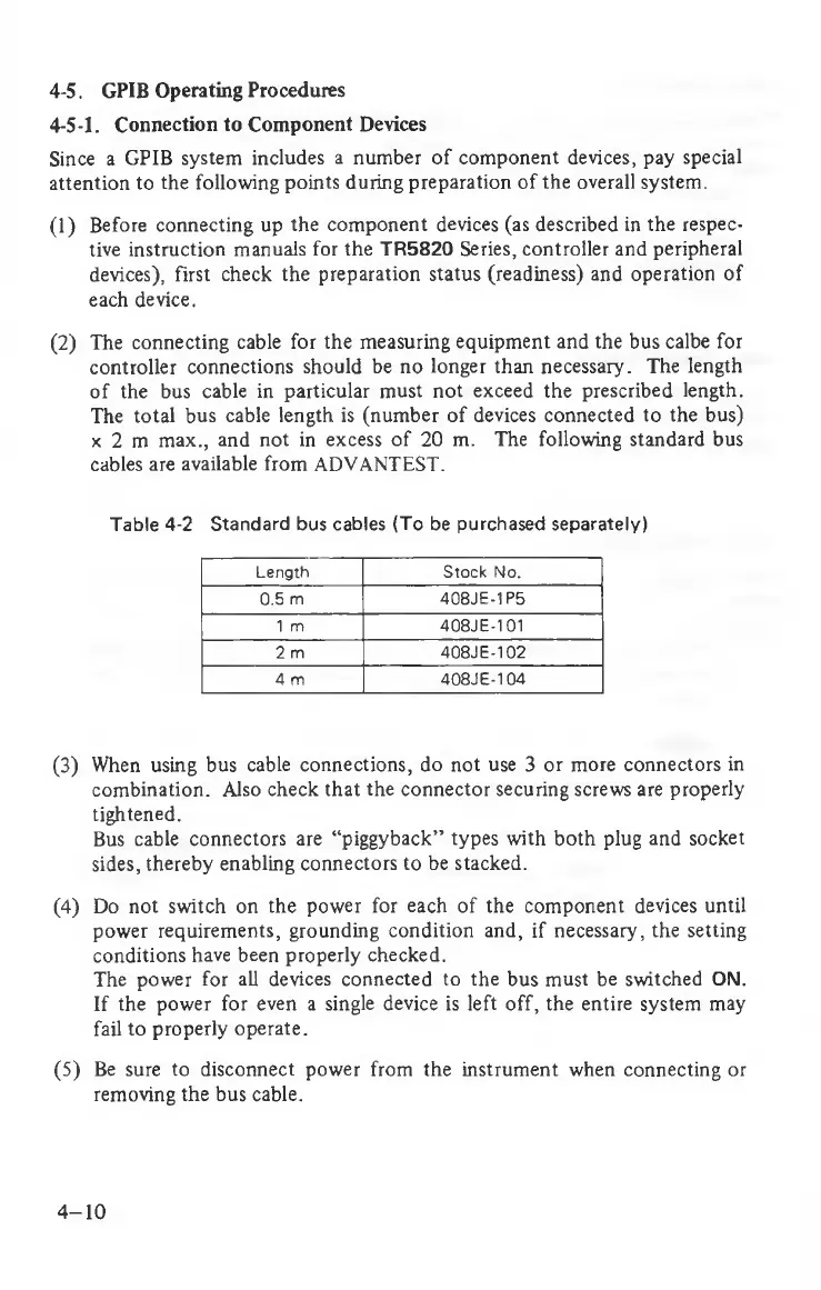
(2) The connecting cable for the measuring equipment and the bus calbe for
controller connections should be no longer than necessary. The length
of the bus cable in particular must not exceed the prescribed length.
The total bus cable length is (number of devices connected to the bus)
x 2 m max., and not in excess of 20 m. The following standard bus
cables are available from ADVANTEST.
Table 4-2 Standard bus cables (To be purchased separately)
Length Stock No.
0.5 m 408JE-1P5
1 m
408JE-101
2 m
408JE-102
4 m 408JE-104
(3) When using bus cable connections, do not use 3 or more connectors in
combination. Also check that the connector securing screws are properly
tightened.
Bus cable connectors are “piggyback” types with both plug and socket
sides, thereby enabling connectors to be stacked.
(4) Do not switch on the power for each of the component devices until
power requirements, grounding condition and, if necessary, the setting
conditions have been properly checked.
The power for all devices connected to the bus must be switched ON.
If the power for even a single device is left off, the entire system may
fail to properly operate.
(5) Be sure to disconnect power from the instrument when connecting or
removing the bus cable.
4-10