10 AI-5620 User Guide
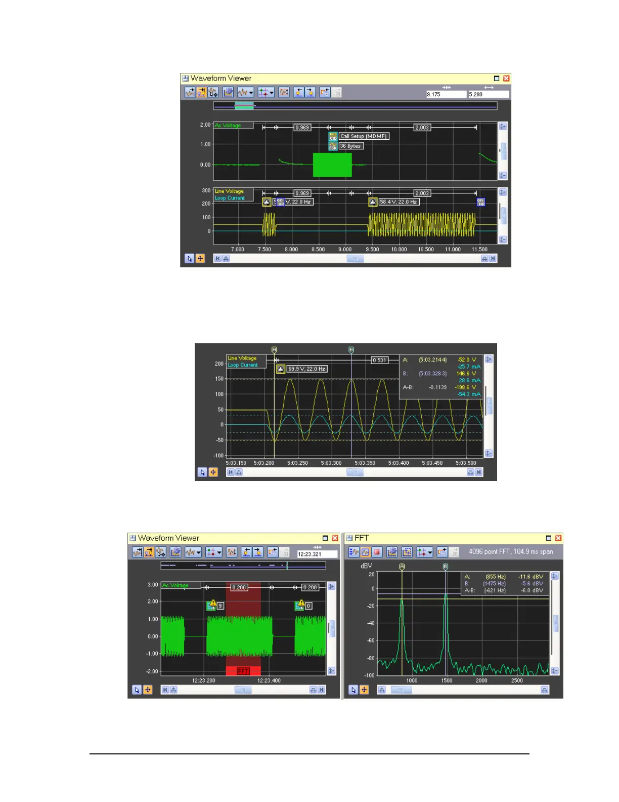
1. Capture of the waveforms present during an on-hook Caller ID transmission. The top
green trace shows the AC coupled channel containing the FSK modulated data, while the
bottom yellow and blue traces show the line voltage and loop current channels
respectively.
2. Capture of ringing signal with a ringing load applied. Cursors are used to measure the
positive and negative peaks for both the line voltage and loop current.
3. Viewing the FFT of a captured DTMF digit. The waveform view highlights in a red
background color the time range used for the FFT calculation. Its position is always