Advent Instruments Inc. 4. Technical Overview
AI-5620 User Guide 13
4. Technical Overview
4.1 Block Diagrams
The AI-5620 Terminal Equipment Simulator consists primarily of highly programmable
AC and DC termination impedances coupled with circuits used in monitoring the
telephone line voltage and current conditions.
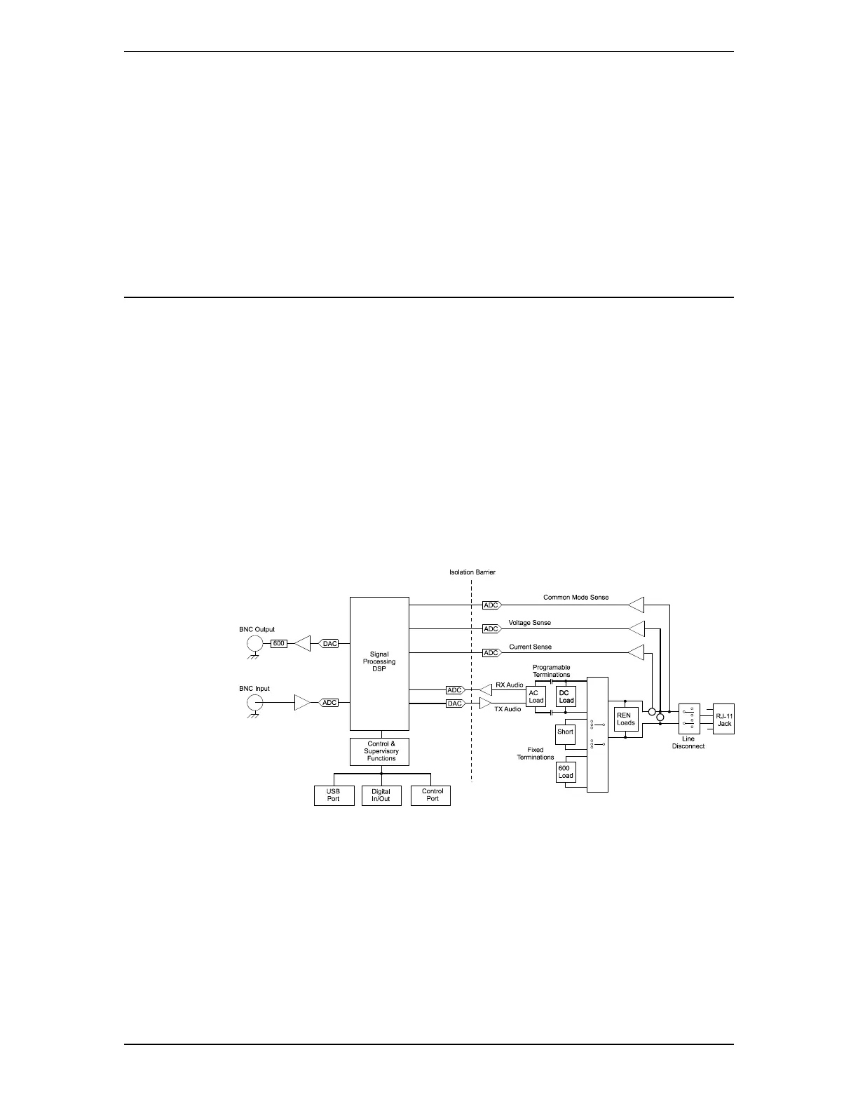
The following figure shows the major functional blocks of the AI-5620. At its center is
the signal processing block responsible for controlling the line interface's DC and AC
characteristics, generating signals, and monitoring the line conditions.
Five different terminations may be applied to the line in various combinations. The
terminations are a programmable DC resistance, programmable AC impedance, fixed 600
ohm resistance, zero ohm resistance, and programmable ringing loads. By engaging the
programmable AC impedance termination, a wide range of signals may be applied to the
line. This includes DTMF dialing, Bell 202 or V.21 FSK, broadband white noise, or
playback of arbitrary waveforms.
At all times, the AI-5620 monitors and records the metallic line voltage, common mode
voltage, and loop current. Measured AC signals are processed for the detection of a wide
range of telephony related events such as DTMF digits, Caller ID FSK messages,
CAS/DTAS, or metering pulse tones.
The next diagram provides a more detailed view of the various AC and DC terminations
that can be applied across the tip/ring leads. All of the terminations are categorized into
four groups. They are AC impedance, off-hook resistance, on-hook resistance, on-hook
ringing loads.