16 AI-5620 User Guide
4.2 Indicators & Connections
The AI-5620 front panel is quite simple and contains four LED indicators and one RJ-11
telephone line interface jack.
The two left side indicators Ready and Communication show the status of the unit and
communication activity respectively.
Under normal operation the Ready indicator is constantly illuminated. However, if the
AI-5620's USB port is not connected to an operating PC it briefly blinks once every one
to two seconds. In situations where an internal fault is detected, the Ready indicator will
start flashing. When flashing, the Ringing and Off-Hook indicators are used to signal the
specific fault condition. See Appendix B: Error Codes on page 26 for more information
on the fault conditions.
The communication LED briefly illuminates anytime data is either sent to the PC or
received from the PC.
When the Ready indicator is illuminated (no fault condition), then the two right side
LED's show when the AI-5620 has detected ringing or when the line interface is in the
off-hook state. Ringing is detected if an AC voltage exceeding 40 Vrms with a frequency
in the range of 10 to 100 Hz. is measured. The AI-5620 illuminates the Off-Hook LED
when one of the following terminations is engaged:
• Programmable DC resistance (50 to 1000 )
• Fixed 600 termination resistor
• Short circuit termination
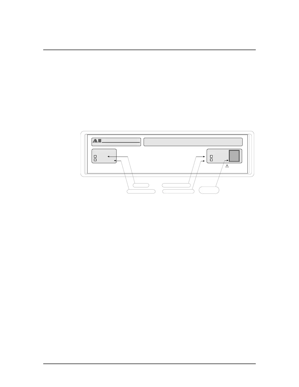
The next figure shows the configuration of the AI-5620 rear panel. The right most IEC
power jack is used to power the unit and the switch beside it allows the unit to be turned
on or off while connected to the AC mains. The connection to the PC (or any other host)
is made via the USB type B connector.