Advent Instruments Inc. 4. Technical Overview
AI-5620 User Guide 15
Note, if any of the ringing loads are enabled, the signal generator AC terminations are
automatically disconnected.
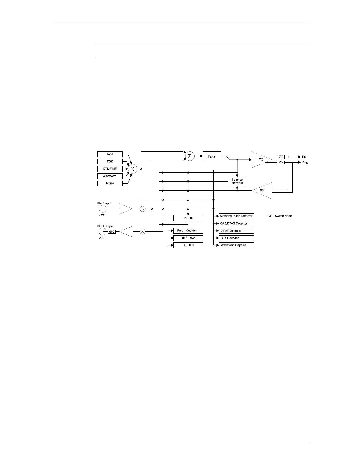
From the stand point of AC signals, the following diagram shows the signal routing flow
within the AI-5620.
All signals presented to the line interface are created by either the various internal signal
generators or from the rear panel BNC input connector. The signal generators are
capable of producing simple tones, FSK modulated data (Bell 202 or V.21), DTMF, MF
(multi-frequency), broadband white noise, or arbitrary waveform playback. The sum of
all the generators can be combined with the rear panel BNC input signal and routed to the
line interface. Optionally, varying degrees of echo can be applied to the signal before it
is sent to the line.
The AI-5620 has three primary signal sinks. They are a signal measurement meter, signal
analyzer, and the rear panel BNC output connector.
The signal measurement meter provides continually updated readings of RMS level,
frequency, and THD+N. Prior to making any measurements, it can apply any one of a
number of filters. These include adjustable low pass, high pass, band pass, and notch
filters.
The signal analyzer performs a number of different tasks. They are detecting DTMF
digits, detecting CAS/DTAS tones, detecting metering pulses, decoding Bell 202 or V.23
FSK modulated data, and recording AC signal waveforms.
The BNC output connector provides a means of externally monitoring the signals present
at either the line interface or other locations within the signal routing flow.
The signal source for the measurement meter, analyzer, and BNC output is selected from
one of five different signal points. They are either the generator output, telephone
interface TX signal, telephone interface RX signal, BNC input signal, and the telephone
interface RX hybrid output signal.
The RX hybrid output signal is generated from a balance network which attempts to
cancel the TX signal by simulating the source impedance of AI-5620 and the expected
load impedance of any device connected to the line interface. This provides a means of
measuring or monitoring signals that are generated by only the connected equipment, and
not the AI-5620.